
Instruction Manual


Instruction Manual
D103434X012
Blocks
November 2014
132
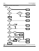
For a SELECT_TYPE [19] of Average, SELECTED [21] indicates the number of inputs used in the average calculation.
When the block mode is Manual, SELECTED [21] is set to 0.
Alarm Detection
A block alarm will be generated whenever the BLOCK_ERR [6] has an error bit set. The types of block error for the PID
block are defined above.
Process alarm detection is based on OUT [7] value. You can configure the alarm limits of the following standard
alarms:
D High (HI_LIM [40])
D High high (HI_HI_LIM [38])
D Low (LO_LIM [42])
D Low low (LO_LO_LIM [44])
In order to avoid alarm chattering when the variable is oscillating around the alarm limit, an alarm hysteresis in percent
of the PV span can be set using the ALARM_HYS [36] parameter. The priority of each alarm is set in the following
parameters:
D HI_PRI [39]
D HI_HI_PRI [37]
D LO_PRI [41]
D LO_LO_PRI [43]
ACK_OPTION [35] is used to set automatic acknowledgement of alarms.
ALARM_SUM [34] indicates the current alert status, unacknowledged states, and disabled states of the alarms
associated with the function block.
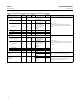
Alarms are grouped into five levels of priority, as shown in table B‐32.
Table B‐32. ISEL Function Block Alarm Priorities
Priority Number Priority Description
(1)
0 The priority of an alarm condition changes to 0 after the condition that caused the alarm is corrected.
1
An alarm condition with a priority of 1 can be recognized by the system. The device monitors the alarm but does not report it
until requested by the host system.
2
An alarm condition with a priority of 2 is reported to the operator, but generally does not require operator attention (such as
diagnostics and system alerts).
3‐7 Alarm conditions of priority 3 to 7 are advisory alarms of increasing priority.
8‐15 Alarm conditions of priority 8 to 15 are critical alarms of increasing priority.
1. The priority classes “advise” and critical” have no relationship to Plant Web Alerts.