
Instruction Manual


Instruction Manual
D103434X012
Blocks
November 2014
113
Analog Output (AO) Function Block
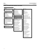
The Analog Output (AO) function block (figure B‐10) assigns an output value to a field device through a specified I/O
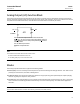
channel. The block supports mode control, signal status calculation, and simulation. Figure B‐11 illustrates the internal
components of the AO function block, and table B‐27 lists the definitions of the block parameters.
Figure B‐10. Analog Output (AO) Function Block
B2716‐1
BKCALOUT
OUT
CAS
IN
BKCAL
OUT = The value and status required by the BKCAL IN input of
another block to prevent reset windup and to provide bumpless transfer to
closed loop control.
CAS
IN = The remote setpoint value from another function block.
OUT
= The block output and status.
AO
READBACK
READBACK
= Compensation value.
Note
The AO block actual mode will not move to Auto unless:
D
Resource Block actual mode is Auto, and
D
AO SHED_OPT [27] is set to a non‐zero value.
Modes
The Analog Output function block supports the following modes:
D Manual (Man)—You can manually set the output to the I/O channel through the OUT [9] attribute. This mode is used
primarily for maintenance, calibration and diagnostics.
D Automatic (Auto)—The block output (OUT [9]) reflects the target operating point specified by the setpoint (SP [8])
attribute. Typically the setpoint is set by the user.
D Cascade (Cas)—The SP [8] attribute is set by another function block through a connection to CAS_IN [17]. The SP [8]
value is used to set the OUT [9] attribute automatically. This is the most frequently used mode in the digital level
controller.
Note
The transducer block must be in Auto for the mode to go to AUTO, CAS, MAN, or RCAS.