
Instruction Manual


Instruction Manual
D103434X012
Blocks
November 2014
106
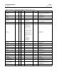
Figure B‐9. Discrete Input Proximity Detection Function (Snap Acting Controller)
DISCRETE INPUT
SET (FALLING
POINT)
DISCRETE INPUT
CLEARED
(RISING POINT)
RISING DEADBAND
FALLING DEADBAND
LEVEL
DEPICTS RISING POINT ACTIVE
DEPICTS FALLING
POINT ACTIVE
DI Rising
DI Falling
TIME
TIME
Table B‐18. Channel Selection for the Discrete Input Function Block
Selection Transducer Block Parameter
(1)
Transducer Block Index Number Bit Number
(2)
6 DI_1_READBACK 47 0: Not active, 1: Active
7 DI_2_READBACK 51 0: Not active, 1: Active
1. Refer to table B‐54 for parameter descriptions.
Field Value Processing
The Invert bit of the IO_OPTS [13] parameter may be used to logically invert the value of FIELD_VAL_D [17] before it is
stored as PV_D [7]. PV_FTIME [16] may
be used to set the length of time that FIELD_VAL_D [17] must be in a new state before that new state is reflected in
PV_D. The PV_D [7] value goes to the mode switch where it becomes OUT_D [8] when the actual mode is AUTO.
OUT_D [8] is also tested for an alarm state.
Note
Invert is the only I/O option that the DI block supports. You can set the I/O option only when the block mode is Out of Service.
Alarm Detection
To select the state that initiates an input alarm, and to set discrete alarm substatus in the output, configure the
DISC_LIM [23] parameter. You can enter any value between 0 and 255. A value of 255 disables the alarm. When
OUT_D [8] matches the DISC_LIM [23] state, the discrete value of an alarm is set.