
Data Sheet

DLC3020f Digital Level Controller
D103433X012
Product Bulletin
11.2:DLC3020f
November 2014
3
Specifications (continued)
Alerts and Diagnostics
Electronic Alerts advise when there is an electronic
error in memory
Operational Range Alerts notify when PV range and
sensor range changes might affect calibration
Rate Limit Alerts indicate rapid rise or fall in displacer,
which can signify abnormal operating conditions
RTD Alerts show health and condition of connected
RTD
Sensor Board Alerts indicate if the device is operating
above or below maximum recommended limits;
advises if the electronic sensor electronics cannot
communicate properly
Input Compensation Error Alerts advise of “Bad” or
“Uncertain” status of AO connection or setup.
Simulate Function
Simulate Active, when enabled, simulates an active
alert without making it visible.
Operating Limits
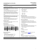
Process Temperature: See figure 1
Ambient Temperature
(1)
and Humidity
Conditions Normal Limits
Transport and
Storage Limits
Nominal
Reference
Ambient
Temperature
-40 to 80_C
(-40 to 176_F)
-40 to 85_C
(-40 to 185_F)
25_C
(77_F)
Ambient
Relative
Humidity
0 to 95% (non-condensing) 40%
Electrical Classification
Hazardous Area
CSA— Intrinsically Safe, Explosion‐proof,
Division 2, Dust Ignition‐proof
FM— Intrinsically Safe, Explosion‐proof,
Non‐Incendive, Dust Ignition‐proof
ATEX— Intrinsically Safe, Flameproof, Type n
IECEx— Intrinsically Safe, Flameproof, Type n
Electrical Housing
CSA— Type 4X
FM— NEMA 4X, IP66
ATEX— IP66
IECEx— IP66
Mounting Positions
Digital level controllers can be mounted right‐ or
left‐of‐displacer (the position of the instrument when
you are looking at the LCD relative to the displacer)
Construction Materials
Case and Cover: Low‐copper aluminum alloy
Internal: Plated steel, aluminum, and stainless steel;
encapsulated printed wiring boards; Neodymium Iron
Boron Magnets
Electrical Connections
Two 1/2‐14 NPT internal conduit connections; one on
bottom and one on back of terminal box. M20
adapters available.
Weight
Less than 2.7 Kg (6 lbs)
Dimensions
Refer to Fisher Bulletin 34.2:249
for sensor, level
controller, and transmitter dimensions
Options
J Heat insulator J Mountings for Masoneilant,
Yamatake, and Foxborot‐Eckhardt sensors available
1. The pressure/temperature limits in this manual and any applicable standard or code limitation for valve should not be exceeded.