
Data Sheet


D4 Valve
D103039X012
Product Bulletin
51.2:D4
November 2013
6
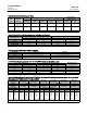
Table 3. Valve Sizes and Connection Styles
VALVE
SIZE,
NPS
PORT
DIAMETER,
(INCHES)
SCREWED RAISED FACE (RF) FLANGED
RING TYPE JOINT
(RTJ) FLANGED
4250 psi CL150 CL300 CL600
CL900 and
1500
CL600
CL900 and
1500
1
0.25, 0.375,
0.5, 0.75
X X X X X X X
2
0.25, 0.375,
0.5, 0.75, 1,
1.25
X X X X X X X
X = Available construction.
Table 4. Fisher D4 Control Valves Approximate Weights, Kg (Pounds)
Valve Body S ize, NPS
Pneumatic Electric
1 2 1 2
Screwed 32 (71) 39 (87) 22 (49) 29 (64)
CL150 34 (74) 39 (86) 24 (52) 29 (63)
CL300 and 600 37 (81) 48 (106) 27 (59) 33 (73)
CL900 and 1500 50 (110) 66 (146) 40 (88) 51 (113)
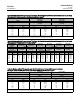
Table 5. Typical Combinations of Metal Trim Parts
DESIGNATION VALVE PLUG SEAT RING
Standard S41600 hardened to 38 HRC minimum S17400
Sour S17400 (NACE MR0175/ISO 15156) S17400 (NACE MR0175/ISO 15156)
Tungsten Carbide Tungsten carbide / S17400 (NACE MR0175/ISO 15156) Tungsten carbide / S17400 (NACE MR0175/ISO 15156)
Table 6. Fisher D4 Environmental Limits for NACE MR0175/ISO 15156 with Sour Trim
MAXIMUM TEMPERATURE MAXIMUM H
2
S PARTIAL PRESSURE
COMPATIBLE WITH
ELEMENTAL SULFUR?
_C _F MPa psia
204 400 1.4 200 No
199 390 2.3 330 No
191 375 2.5 360 No
149 300 2.8 400 No
135 275 No Limit Yes
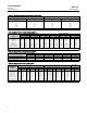
Table 7. Maximum Shutoff Pressure Drops
(1)
for Fisher D4 Control Valves with Pneumatic Actuator (Spring-to-Close)
When Used with Typical Control Instrumentation
(2)
INPUT SIGNAL TO
ACTUATOR
0to1.2Bar
(0 to 18 Psig)
0to1.4Bar
(0 to 20 Psig)
0to2.0Bar
(0 to 30 Psig)
0to2.3Bar
(0 to 33 Psig)
0to2.4Bar
(0 to 35 Psig)
0to3.4Bar
(0 to 50 Psig)
SPRING Light Rate Heavy Rate
INITIAL SPRING
SETTING
0.77 Bar
(11.2 Psig)
0.77 Bar
(11.2 Psig)
0.85 Bar
(12.4 Psig)
1.05 Bar
(15.3 Psig)
1.18 Bar
(17.1 Psig)
1.18 Bar
(17.1 Psig)
PORT DIAMETER Maximum Pressure Drop
mm Inches Bar Psi Bar Psi Bar Psi Bar Psi Bar Psi Bar Psi
6.4
9.5
12.7
19.1
25.4
31.8
0.25
0.375
0.5
0.75
1
1.25
293
(3)
293
(3)
191
80
42
25
4250
(3)
4250
(3)
2765
1160
610
365
293
(3)
293
(3)
191
80
42
25
4250
(3)
4250
(3)
2765
1160
610
365
293
293
219
92
49
30
4250
4250
3180
1340
715
430
293
293
288
123
67
41
4250
4250
4180
1785
965
590
293
293
293
143
78
48
4250
4250
4250
2080
1130
700
293
293
293
143
78
48
4250
4250
4250
2080
1130
700
1. The p ressure or temperature limits in the referenced tables and any applicable ASME code limitations should not be exceeded.
2. For example, use the co lumn marked 0-1.4 bar (0-20 psig) for a 0.21-1.0 bar (3-15 psig) pneumatic controller with 1.4 bar (20 psig) supply pressure.
3. For applications with downstream pressure in excess of 196 bar (2845 psig), use 196 bar (2845 psig) for Maximum Shutoff Pressure.