
Brochures and Data Sheets

• Voltage surge protector
• Main Disconnect Switch sized for connected motor
horsepower and voltage
• Fire pump Circuit Breaker
• Single handle Isolating Disconnect Switch/Circuit
Breaker mechanism
• Motor contactor
• Emergency Manual Run Mechanism to mechanically
close motor contactor contacts in an emergency condi-
tion
• Built-in Start and Stop push-buttons to bypass auto-
matic start circuits
• Minimum Run Timer / Off Delay Timer
• Daylight Savings Time Option
• Weekly Test Timer
• Elapsed Time Meter
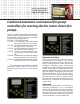
• Door mounted display/interface panel featuring a 128 x
64 pixel backlit LCD Graphical Display, Membrane Type
User Control Push-buttons and easy to read LED Indica-
tors for:
• POWER AVAILABLE
• ALARM
• TRANSFER SWITCH NORMAL (If unit ordered with
Automatic Power Transfer Switch)
• TRANSFER SWITCH EMERGENCY (If unit ordered with
Automatic Power Transfer Switch)
• SYSTEM PRESSURE LOW
• PUMP RUNNING
• DELUGE OPEN
• REMOTE START
• INTERLOCK ON
• FAIL TO START
• MOTOR OVERLOAD
• EMERGENCY ISO SWITCH OFF (If unit ordered with
Automatic Power Transfer Switch)
• PHASE FAILURE
• PHASE REVERSAL
• AUTOMATIC SHUTDOWN DISABLED
• OVERVOLTAGE
• UNDERVOLTAGE
• Digital Pressure Display
• USB Host Controller and Port
• Solid State Pressure Transducer
• Data Log
• Event Log (3000 Events)
• True RMS Metering with simultaneous 3 Phase Display of
Amps, Volts, Frequency, Pressure and Alarm Messages
• Disk Error message
• Disk Near Full message
• Pressure Error message
• Motor Over 320% message
• Local Start message
• Remote Start message
• Emergency Start message
• Fail To Start message
• Undervoltage message
• Overvoltage message
• NEMA Type 2 enclosure
• Suitable for use as Service Equipment
• Each standard controller comes with user configurable
options for:
• Interlock Alarm • Low Pressure Audible
•Low Suction • Pump Run
• User Defined Input • Weekly Test
Standard features include:
Digital Status/Alarm Messages
The digital display indicates text messages for
the stats and alarm conditions of:
• Motor On • Sequential Start Time
• Minimum Run Time • Local Start
/ Off Delay Time • Remote Start
• Fail to Start • System Battery Low
• Under Voltage • Over Voltage
• Locked Rotor Trip • Over Frequency
• Emergency Start •Motor Over 320%
• Drive Not Installed • Motor Overload
• Disk Error • Printer Error
• Disk Near Full • Pressure Error
The Sequential Start Timer and Minimum Run
Timer/Off Delay Times are displayed as numeric
values refl ecting the value of the remaining
time.
LED Visual Indicators
LED indicators, visible with the door closed,
indicate:
• Power Available • Alarm
• Pump Running • System Pressure Low
• Remote Start • Transfer Switch Normal
• Deluge Open • Transfer Switch Emergency
• Phase Failure • Phase Reversal
• Interlock On • Fail To Start
• Motor Overload • Emerg. Iso. Switch Off
• Automatic Shutdown Disabled
• Overvoltage • Undervoltage
the latest editions of NFPA 20, Installation of
Centrifugal Fire Pumps, and NFPA 70, National
Electrical Code.