
Service manual

1-12-1 T5553PIN
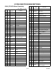
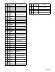
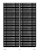
IC PIN FUNCTION DESCRIPTIONS
IC201 (TV/VCR Micro Controller)
“H” ≥ 4.5V, “L” ≤ 1.0V
Pin
No.
IN/
OUT
Signal
Name
Function
1 IN LD-SW Loading Switch Input
2 - NU Not Used
3 IN P-SAFETY 2
Power Supply Failure
Detection 2
4 IN P-SAFETY 3
Power Supply Failure
Detection 3
5 IN KEY0 Key 0 Input
6 IN KEY1 Key 1 Input
7 IN END-SENS End-Sensor
8 IN AFT-IN AFT Input
9 IN ST-SENS Start-Sensor
10 IN V-ENV Video Envelope Input
11 - NU Not Used
12 OUT SP-MUTE Speaker Mute Output
13 OUT DV-SYNC Artificial V-Sync Output
14 IN REMOTE Remote Signal Input
15 OUT ROTA
Color Phase Rotary
Changeover SIgnal
16 - V-H-SW(NU) Not Used
17 - NU Not Used
18 OUT RF-SW
Video Head Switching
Pulse
19 - NU Not Used
20 - NU Not Used
21 - IF-MUTE IF-MUTE Signal
22 OUT REC-LED
Recording LED Control
Signal
23 OUT REC-LED
Recording LED Control
Signal
24 - NU Not Used
25 - NU Not Used
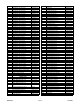
26 - FM/TV-SW FM/TV-SW Signal
27 - NU Not Used
28 - NU Not Used
29 - NU Not Used
30 - NU Not Used
31 OUT P-ON-H Power On Signal at High
32 - NU Not Used
33 IN
REC-
SAFETY
Record Protection Tab
Detection
34 IN RESET
System Reset Signal
(Reset=”L”)
35 IN XC-IN Sub Clock 32 kHz
36 OUT XC-OUT Sub Clock 32 kHz
37 - TIMER+5V Vcc
38 IN X-IN Main Clock Input
39 OUT X-OUT Main Clock Output
40 - GND GND
41 OUT SPOT-KILL Counter-measure for Spot
42 - NU Not Used
43 IN CLKSEL Clock Select (GND)
44 OUT D-REC-H Delayed Record Signal
45 IN I2C-OPEN
White Balance Adjust
Mode Judgment
46 - GND GND
47 - NU Not Used
48 - NU Not Used
49 - GND OSD GND
50 - GND GND
51 - NU Not Used
52 - NU Not Used
53 - P-ON+5V OSD Vcc
54 - HLF HLF
55 IN V-HOLD VHOLD
56 IN CV-IN Video Signal Input
57 - GND GND
58 IN H-SYNC H-SYNC Input
59 IN V-SYNC V-SYNC Input
60 OUT OSD-BLK Output for Picture Cut off
61 - NU Not Used
62 OUT OSD-B Blue Output
63 OUT OSD-G Green Output
64 OUT OSD-R Red Output
65 OUT A-MUTE Audio Mute Output
66 OUT C-F/R
Capstan Motor FWD/REV
Control Signal
Pin
No.
IN/
OUT
Signal
Name
Function