Softing Linking Device Manual for Configuration, Installation and Maintenance V1.31 Date: July 24th, 2013 Softing Industrial Automation GmbH Richard-Reitzner-Allee 6 85540 Haar Germany Phone (++49) 89 45656-0 Fax (++49) 89 45656-399 Copyright 2013 by Softing Industrial Automation GmbH All rights reserved.
© 2013 SOFTING Industrial Automation GmbH No part of this document may be reproduced (printed material, photocopies, microfilm or other method) or processed, copied or distributed using electronic systems in any form whatsoever without prior written permission of SOFTING Industrial Automation GmbH. The manufacturer reserves the right to make changes to the scope of supply as well as changes to technical data, even without prior notice.
Softing Linking Device – Manual for Configuration, Installation and Maintenance Table of Contents 1 General Notes 7 1.1 Scope of Delivery 7 1.2 Safety Notes 7 1.3 Intended Use 7 1.4 System Requirements 7 1.4.1 Operating Systems 7 2 Hardware Installation 8 2.1 Overview Hardware – FG-110 FF 8 2.2 LED Block – Meaning 8 2.3 Power Supply 9 2.4 Ethernet Port 9 2.5 Modbus 10 2.5.1 MODBUS TCP 10 2.5.2 MODBUS serial (RS232 / RS485) 10 2.6 FF H1 fieldbus connection 11 2.
Softing Linking Device – Manual for Configuration, Installation and Maintenance 4.5 23 4.5.1 23 4.5.1.1 23 4.5.1.2 25 4.5.1.3 26 4.5.1.4 27 4.5.2 28 4.5.2.1 28 4.5.2.
Softing Linking Device – Manual for Configuration, Installation and Maintenance 5.1.4.4 Parameter View 46 5.1.4.5 Schedule View 46 5.1.5 The Trace Log 46 5.1.6 List and properties view 47 5.1.6.1 Device Types 47 5.1.6.2 Block Types 48 5.1.6.3 Devices 49 5.1.6.4 Blocks 50 5.1.6.5 Properties 50 5.1.7 Filtering the contents 51 5.2 General Information 51 5.2.1 Floating windows 51 5.2.2 Objects within the Network Configuration 52 5.2.3 Tag Names 52 5.2.
Softing Linking Device – Manual for Configuration, Installation and Maintenance 5.8.2.7 Block types first approach 72 5.8.3 Schedule View 73 5.9 Handling Host devices 73 6 Error handling and troubleshooting 74 7 Appendix A - Bus Parameter Configuration 76 7.1 Bus parameters relevant for H1 devices 76 7.2 Bus parameters relevant for H1 Links 77 8 Glossary 79 8.1 General remarks of the user manual 79 8.2 Networking definitions 80 8.
Softing Linking Device – Manual for Configuration, Installation and Maintenance General Notes 1 General Notes Please read this document thoroughly from beginning to end before starting installation to protect users from injury and to prevent misuse or damage to the Linking Device. 1.
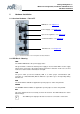
Softing Linking Device – Manual for Configuration, Installation and Maintenance Hardware Installation 2 Hardware Installation 2.1 Overview Hardware – FG-110 FF LED Block – see chapter 2.2 Power Supply – see chapter 2.3 Up to 4 H1 Segments – see chapter 2.6 Serial Port RS232 – see chapter 2.5 Ethernet Port – see chapter 2.4 Fig 2.1-1 Overview Hardware – FG-110 FF power and data connections 2.
Softing Linking Device – Manual for Configuration, Installation and Maintenance Hardware Installation 2.3 Power Supply The Linking Device is powered by 24 V DC. The power supply plug connector is included in the delivery. The power supply socket connector on the front panel is labeled DC 24V-. L+ M Fig 2.3-1 Linking Device Power Supply The two power supply terminals are labeled L+ and M. L+ must be connected to 24V and M to 0V. The two terminals are provided with an internal reverse-polarity protection.
Softing Linking Device – Manual for Configuration, Installation and Maintenance Hardware Installation The Ethernet port corresponds to the standards IEEE 802.3 100BASE-TX/10BASE-T and supports auto negotiation. The pin assignment corresponds to MDI (Medium Dependent Interface). Pin MDI Signal Pinout (Standard Ethernet Cable) 1 TD+ 2 TD- 3 RD+ 4 Not used 5 Not used 6 RD- 7 Not used 8 Not used Table 2.4-1 Ethernet Pins 2.5 Modbus 2.5.
Softing Linking Device – Manual for Configuration, Installation and Maintenance Hardware Installation Stahl. You will find this manual on the CD-ROM or on the internet web page http://www.rstahl.com 2.6 FF H1 fieldbus connection The fieldbus terminals are mounted in 4 sets of three terminals for the positive and negative conductors and a shield (FF1 – FF4). Although the Linking Device is not polarity sensitive, other components in the segment such as junction blocks may require correct polarity.
Softing Linking Device – Manual for Configuration, Installation and Maintenance Hardware Installation Fig 2.7-1 Mounting the Linking Device ready for use: the SOFTING Foundation Fieldbus Interface Module FIM 110 The Linking Device is convection-cooled. It therefore needs to be installed in such a way that the ventilating ducts are at the top and bottom of the unit. i Please ensure against the direct contact with the sunlight. 2.
Softing Linking Device – Manual for Configuration, Installation and Maintenance Ethernet Network Configuration 3 Ethernet Network Configuration 3.1 Linking Device IP address Configuration The Linking Device is delivered with a pre-configured IP address 192.168.177.177. It must be assigned an IP address from your LAN address range. Furthermore, subnet mask and gateway IP address must be set. To configure the Linking Device a private network between a PC and the Linking Device must first be established.
Softing Linking Device – Manual for Configuration, Installation and Maintenance Linking Device FG-110 FF - Internal Web Server 4 Linking Device FG-110 FF - Internal Web Server The internal web server of the Linking Device FG-110 FF offers the possibilities to configure the Linking Device (like IP address settings or Modbus mapping), to get diagnostic information on the fieldbus or Modbus as well as to monitor process values of the connected field devices. 4.
Softing Linking Device – Manual for Configuration, Installation and Maintenance Linking Device FG-110 FF - Internal Web Server Fig 4.1-1 Starting Screen 4.2 Information 4.2.1 When you click on you will see the contact address of Softing Industrial Automation GmbH on the free partition on the right of the screen. This view is the default Homepage. Fig 4.2-1 Contact 4.2.
Softing Linking Device – Manual for Configuration, Installation and Maintenance Linking Device FG-110 FF - Internal Web Server right partition on the right of the screen. Here you can find the numbers of the several Linking Device modules which are important for questions relating to the support of Softing Industrial Automation GmbH. Fig 4.2-2 Version 4.2.3 Click on and you find a link to download the manual from the Softing webpage Fig 4.
Softing Linking Device – Manual for Configuration, Installation and Maintenance Linking Device FG-110 FF - Internal Web Server 4.2.4 Click on to obtain topical information about licenses which are used in the Linking Device. Fig 4.2-4 Actual information for the customer 4.3 Under the menu item the headers , , and are listed.
Softing Linking Device – Manual for Configuration, Installation and Maintenance Linking Device FG-110 FF - Internal Web Server Fig 4.3-1 System - actual Information of the Linking Device state 4.3.2 The table lists the main information the system has got about the connected subnet. Fig 4.3-2 Data of the Internet protocol 4.3.
Softing Linking Device – Manual for Configuration, Installation and Maintenance Linking Device FG-110 FF - Internal Web Server Underneath it another table shows which segment (H1 Link) of the Linking Device (FG-110 FF) is occupied and how many FF-H1 devices are connected under each segment. Additional, for each available FF-H1 device the tag name is shown. So, the this table provide a simple live list of the FF-H1 network. Please note that this list will be updated just be clicking on “Fieldbus” again.
Softing Linking Device – Manual for Configuration, Installation and Maintenance Linking Device FG-110 FF - Internal Web Server ● Framing Errors: Number of framing errors ● Checksum Errors: Number of checksum errors Fig 4.3-4 Fieldbus Statistics (H1 and HSE) The second table shows statistical data for each of the HSE Links.
Softing Linking Device – Manual for Configuration, Installation and Maintenance Linking Device FG-110 FF - Internal Web Server The menu item shows statistical data of a Modbus connected on a serial interface. First messages and CRC errors from received data are listed. Then messages and error responses from the transmitted data are listed. RS232 needs a converting unit RS232/RS485 and a separate data connection between Linking Device and Modbus.
Softing Linking Device – Manual for Configuration, Installation and Maintenance Linking Device FG-110 FF - Internal Web Server Fig 4.3-6 Modbus TCP Statistics 4.4 Click Options to display the point pages and point data. 4.4.1 Point Pages provide a means to view the Process Value (PV) or Output of a Function Block and its status on one or more web pages. Multiple pages can be configured to fit the application and to keep track of the different parts of the plant.
Softing Linking Device – Manual for Configuration, Installation and Maintenance Linking Device FG-110 FF - Internal Web Server 4.4.2 Next click to see the details of all available point pages displayed for the selected page. Fig 4.4-2 Monitor Point Data – all Data of your plant will be shown 4.5 The menu item is a very important item of the Linking Device web site.
Softing Linking Device – Manual for Configuration, Installation and Maintenance Linking Device FG-110 FF - Internal Web Server 1.) Enable VCR Creation If this feature is “on” then the Linking Device establishes the VCR connection by them self. Please read in the software manual if it is necessary or not.
Softing Linking Device – Manual for Configuration, Installation and Maintenance Linking Device FG-110 FF - Internal Web Server 4.5.1.2 The Linking Device is delivered in a default configuration. To change the default internet protocol settings into assigned values of the chosen subnet in which the installation is running you click . A table which enables you to change settings appears.
Softing Linking Device – Manual for Configuration, Installation and Maintenance Linking Device FG-110 FF - Internal Web Server When you click the button the web site shuts down and the system reboots. The input values will be checked for consistency. If the input values are not consistent, the Linking Device will propose consistent values. You can use the proposed values by clicking or keep the values you entered by selecting .
Softing Linking Device – Manual for Configuration, Installation and Maintenance Linking Device FG-110 FF - Internal Web Server 4.5.1.4 The Linking Device is shipped with default user password. Under this menu item you can change the settings of the user passwords. Due to the jobs the user executes in this web site there are several graduations for admission control. The following standard logins and password are available.
Softing Linking Device – Manual for Configuration, Installation and Maintenance Linking Device FG-110 FF - Internal Web Server You can install user passwords for four user groups. Fill in the new password and confirm your input with a second input. The input mode is always the same for all user groups. When you click the button the passwords will be changed and activated the next time you enter the web site. The administrator can modify any system or field device setting.
Softing Linking Device – Manual for Configuration, Installation and Maintenance Linking Device FG-110 FF - Internal Web Server Fig 4.5-5 Download Firmware and Reboot After a new start the firmware stored in the chosen file is now valid for this configuration. i Please note that while the software download is running the connection between the PC and the Linking Device will not be closed or the power supply of the Linking Device disconnected. This can destroy the Linking Device. 4.5.2.
Softing Linking Device – Manual for Configuration, Installation and Maintenance Linking Device FG-110 FF - Internal Web Server Press the button another window appears on the screen which enables you to search for a folder in your directory on your PC or external store media to store the configuration you have created for the installation for future use. With the button “Erase Configuration” the Linking device can be switched back to factory default settings.
Softing Linking Device – Manual for Configuration, Installation and Maintenance Linking Device FG-110 FF - Internal Web Server If the Linking Device is connected to a network and if you want to use this feature, you can select a timeserver at your facility or one near you geographically to ensure accurate time adjustments. The device will function properly with this feature disabled but data time stamps will be less accurate and time updates must be entered for each Linking Device.
Softing Linking Device – Manual for Configuration, Installation and Maintenance Linking Device FG-110 FF - Internal Web Server Another window appears with a table where the valid Points for this point page are listed. Over the table there is an input box with the name of the point page. If you change this name you get a new point page with all the attributes of the chosen point page. The table below the page name has five columns. The first column is named “Point”.
Softing Linking Device – Manual for Configuration, Installation and Maintenance Linking Device FG-110 FF - Internal Web Server Fig 4.5-10 Select columns and save your selection 4.5.3.3 When you click a table with four possibilities for the first side of the homepage appears on the screen.
Softing Linking Device – Manual for Configuration, Installation and Maintenance Linking Device FG-110 FF - Internal Web Server You choose the chapter for the start web side of the FG-110 FF with a click on the check box beside the desired chapter. When you press the button the input will be activated. The next start of the web application will show you the selected page as your homepage. If you choose the you have to select the desired page.
Softing Linking Device – Manual for Configuration, Installation and Maintenance Linking Device FG-110 FF - Internal Web Server - Device: Devices (PD Tags) on segment In the table below is shown the function block type (Block Type), function block name (Block Name) and the description. With the “Enable” button can be selected if the bock will be displayed in Point Page Monitor or not. By default only block with a block name are enabled. Fig 4.
Softing Linking Device – Manual for Configuration, Installation and Maintenance Linking Device FG-110 FF - Internal Web Server Fig 4.5-14 Change settings of the H1-Links ! 4.5.4.4 Please change these parameters only if you are absolutely sure it is necessary and correct. Otherwise you will lose the Foundation fieldbus communication. Click to define your parameters for the Linking Device. With you activate your inputs.
Softing Linking Device – Manual for Configuration, Installation and Maintenance Linking Device FG-110 FF - Internal Web Server 4.5.5 The Linking Device allows traditional control systems access to modern fieldbus devices as well as over the serial port RS485 and using TCP/IP. These control systems normally include support for the Modbus communication protocol. 4.5.5.
Softing Linking Device – Manual for Configuration, Installation and Maintenance Linking Device FG-110 FF - Internal Web Server 4.5.5.2 Fig 4.5-17 Change settings of the Modbus Mapping The functions of the Modbus mapping in the Linking Device are flexible enough to accommodate most traditional control systems. The Modbus mapping table allows a user to associate the output or input value of an AI or an AO Function Block with any traditional or extended Modbus register.
Softing Linking Device – Manual for Configuration, Installation and Maintenance Linking Device FG-110 FF - Internal Web Server Fig 4.5-18 Import/Export of the Modbus Configuration V1.
Softing Linking Device – Manual for Configuration, Installation and Maintenance FF-CONF Configure your plant 5 FF-CONF Configure your plant By choosing the FF-CONFsetup.exe you will start the installation routine of the FF-CONF program. To start FF-CONF it is not necessary to activate any network access, but without network access online configuration is not necessary. It is possible to create various configurations and store them in external files.
Softing Linking Device – Manual for Configuration, Installation and Maintenance FF-CONF Configure your plant 5.1.1 Caption The caption shows the name FF-CONF, the file name of the active project and the program status offline/online. 5.1.2 Main menu In the maim menu you find the following items specially to administrate and to organize your project. When you click on the right mouse button each of the items of the main menu allows you to activate or deactivate the toolbar. 5.1.2.1 Project 5.
Softing Linking Device – Manual for Configuration, Installation and Maintenance FF-CONF Configure your plant 5.1.2.3 View 5.1-4 View – shows you the displayed contents of the project With you can activate the desired contents like the Network Livelist, Schedule View or intentionally hidden parts of the screen like Trace Log or previously activated views. The tabs for the Network Configuration and the Function Block Application cannot be closed, but can be brought to the foreground. 5.1.2.
Softing Linking Device – Manual for Configuration, Installation and Maintenance FF-CONF Configure your plant Build All Build all first checks the configuration and then builds a download domain if there are no error messages which prevent generation of the download domain. A lot of information, warning and error codes are given in the Trace log. If the build all function is done successfully you can download a device or the whole project. 5.1.2.5 Download needs the online mode.
Softing Linking Device – Manual for Configuration, Installation and Maintenance FF-CONF Configure your plant 5.1.2.6 Online When FF-CONF is started with a new or an existent project FF-CONF is in mode offline. You can configure devices or build your Function Block application in this mode. If you want to see the real installation – the Network Livelist – you must change to the online mode. When you open the livelist with the program automatically changes to online.
Softing Linking Device – Manual for Configuration, Installation and Maintenance FF-CONF Configure your plant Here you define the cycles of the auto save and the handling with Tag names. If you want to add or to change the project description you can do it here even so the project exists. 5.1.2.8 Help The Help function gives you information in different ways. You can call it by pressing the F1 button and you get the Help-Information for the current function you are working with.
Softing Linking Device – Manual for Configuration, Installation and Maintenance FF-CONF Configure your plant Fig 5.1-13 The changed mouse pointer allows you to move the whole configuration picture 5.1.4.2 The tab is always active. Here you configure the communication between the blocks of the H1 devices or the HSE Host. In Function Block Application you can create different groups and applications to structure the whole plant and its various areas.
Softing Linking Device – Manual for Configuration, Installation and Maintenance FF-CONF Configure your plant Fig 5.1-14 Example for Information and Warning in the Trace log The source object of specific messages can be located by double clicking. In this example the HSE Host device parameters are shown. 5.1.
Softing Linking Device – Manual for Configuration, Installation and Maintenance FF-CONF Configure your plant Fig 5.1-15 Content of Device Types, the icons to process them and filters to select Device Types Meaning of the icons below the contents: ● - to sort by Device Name ● - to import a new device, ● - to remove a marked device, ● and the count of total devices found. 5.1.6.2 Block Types Fig 5.
Softing Linking Device – Manual for Configuration, Installation and Maintenance FF-CONF Configure your plant Meaning of the icons below the contents: ● ● - to sort by Manufacturer Name, and the count of total block types found. 5.1.6.3 Devices Fig 5.1-17 Content of Devices, the icons to process them and filters to select Devices Meaning of the icons below the contents: V1.31 ● to sort by Manufacturer Name, Device Name, User Tag, PD Tag ● and tag list count.
Softing Linking Device – Manual for Configuration, Installation and Maintenance FF-CONF Configure your plant 5.1.6.4 Blocks Fig 5.1-18 Content of Blocks, the icons to process them and filters to select Blocks Meaning of the icons below the contents: - to sort by Manufacturer Name, - to look at FB Parameter View ● - to remove Function Block ● - to remove all unused Function Blocks ● - to copy and paste Function Blocks The block view lists all explicitly and implicitly configured function blocks.
Softing Linking Device – Manual for Configuration, Installation and Maintenance FF-CONF Configure your plant Fig 5.1-19 The H1_Device_1 properties of the marked device are shown 5.1.7 Filtering the contents Here you find the possibility to set filters and so you may select the contents shown in the list view. The possibility of filtering is different from item to item and is based on the contents. 5.2 General Information 5.2.1 Floating windows Fig 5.
Softing Linking Device – Manual for Configuration, Installation and Maintenance FF-CONF Configure your plant 5.2.2 Objects within the Network Configuration PC Here you are working online or offline to build your Network Configuration and commission your installation. HSE Subnet Ethernet component which corresponds with the Linking Device. HSE Device HSE Device or Linking Device. Field gateway to the H1 Links and the H1 devices. H1 Link The connective link between the HSE Device and the H1 Devices.
Softing Linking Device – Manual for Configuration, Installation and Maintenance FF-CONF Configure your plant Fig 5.2-2 Hide the units below with a double-click Fig 5.2-3 again Another double-click shows the hidden units 5.2.5 Using the context menu Nearly all objects contain a context menu that allows you to do some of the steps to pattern your Network Configuration or your Function Block Application.
Softing Linking Device – Manual for Configuration, Installation and Maintenance FF-CONF Configure your plant After a short time you see the screen to work with. Fig 5.3-2 Basic screen to load an existent or a new project The above screenshot shows the start screen of FF-CONF if you have never downloaded device descriptions into the device library. 5.4 Managing the Device type library HSE and H1 device types. HSE device descriptions are preconfigured and cannot be changed.
Softing Linking Device – Manual for Configuration, Installation and Maintenance FF-CONF Configure your plant Fig 5.4-1 Select a .cff file for adding an H1 device to the list of Device Types. The device library contains the description of H1 device types. The description of a device (.cff-file, .ffo-file, .sym-file) is either part of the delivery of the H1 device or can be loaded from fieldbus.org: http://www.fieldbus.org/index.
Softing Linking Device – Manual for Configuration, Installation and Maintenance FF-CONF Configure your plant ! Exception: HSE Devices cannot be removed. You get the notification: 5.5 Project handling In the menu item you start the main configuration work of your project. 5.5.1 Create a New Project After the preliminaries you can start a new project. Fig 5.5-1 Starting a new project You choose or . New: The window (2) with the New Projects Dialog appears.
Softing Linking Device – Manual for Configuration, Installation and Maintenance FF-CONF Configure your plant 5.5.2 Save project You can save the project manually whenever you want. You have two options to do this: Fig 5.5-3 Save your project manually If you save your project at object time click the icon in the ToolBar. Fig 5.5-4 Save your project with or with If you want to copy the project with a new name or to another folder use the function .
Softing Linking Device – Manual for Configuration, Installation and Maintenance FF-CONF Configure your plant 5.6 Network configuration The most important part of the project handling is the Network Configuration. You can configure a network in two ways: ● You adapt the network configuration to the real existing installation, ● You configure a planned network without an existing installation and adapt it later. You need only the offline status to do this. Both ways have their advantages.
Softing Linking Device – Manual for Configuration, Installation and Maintenance FF-CONF Configure your plant 5.6.3 Add a Linking Device (HSE) To add a Linking Device to the configuration press the green button selected Linking Device in the list Device Types. to the left of the Fig 5.6-2 Add an HSE Device Below the subnet field an instance of the selected device type appears on the screen.
Softing Linking Device – Manual for Configuration, Installation and Maintenance FF-CONF Configure your plant 5.6.4 Add an H1 Link to a Linking Device Next you add an H1 Link. You use the context menu to do this, using the right mouse button to click on the HSE_Device object. Fig 5.6-5 Add an H1 Link to the HSE Device The H1 Link will be configured, the Port Number and the LinkID are set automatically, but in any case you have to enter a new NodeID.
Softing Linking Device – Manual for Configuration, Installation and Maintenance FF-CONF Configure your plant i The H1 link object represents the port of the linking device with the H1 VFD and the bus parameters common for every device on this link. 5.6.5 Add H1 Device (Field Device) to an H1 Link First you mark the H1 Link to which you want to add an H1 device.
Softing Linking Device – Manual for Configuration, Installation and Maintenance FF-CONF Configure your plant 5.7 Network Livelist The commissioning of your plant needs to adapt the data of your Network Configuration to the installation which really exists (Network Livelist). You must perform the next steps to do this. 5.7.1 Set the online status Fig 5.7-1 The two options to go online When you start the program FF-CONF the function is not active. The Network Livelist is not shown.
Softing Linking Device – Manual for Configuration, Installation and Maintenance FF-CONF Configure your plant When you first change from to the you click on the menu item . Beside the menu items and the new menu item appears and is active. Dependent on the size of the network, FF-CONF needs some time to update the livelist.
Softing Linking Device – Manual for Configuration, Installation and Maintenance FF-CONF Configure your plant In the same way you can pull down the tab Network configuration. So you get two windows in variable size and positions. This way you have the best possibilities to compare and commission your project. You’ll see it below in the screenshot. Fig 5.7-5 Two variable windows to compare and adapt the Network Configuration and the Network Livelist Fig 5.
Softing Linking Device – Manual for Configuration, Installation and Maintenance FF-CONF Configure your plant Device assignment is a time consuming action. During assignment, the device within the network configuration view gets a yellow bullet. The physical device within Network Livelist disappears if the PD tag and/or the node address have changed. As soon as the assignment is accomplished, the physical device is displayed again and the bullet on the configured device turns green.
Softing Linking Device – Manual for Configuration, Installation and Maintenance FF-CONF Configure your plant Copy and paste groups and applications To realize big installation without any problem, and to record all the blocks and connections repeatedly use the possibility to copy and paste groups and applications. Table 5.
Softing Linking Device – Manual for Configuration, Installation and Maintenance FF-CONF Configure your plant ● Select the Function Block application tab. ● Select the blocks tab. The blocks tab contains all configured blocks. These can be filtered. ● Set the profiles filter, for example to AI. All AI blocks are displayed in the list ● Set the selected devices filter to see the AI for a specific device. ● Add the Function Block, for example AI_5 to the Function Block application.
Softing Linking Device – Manual for Configuration, Installation and Maintenance FF-CONF Configure your plant 5.8.2.3 Configure connections Fig 5.8-4 Configure connections Configure a connection by pressing the link buttons: 1. select output pin (H1_Device _3_PID_3.BKCAL_OUT) 2. select input pin (H1_Device _3_PID_3.FF_VAL) 3. click button Configure your application block by block. You cannot reuse a block which has already been used.
Softing Linking Device – Manual for Configuration, Installation and Maintenance FF-CONF Configure your plant Fig 5.8-5 Click FB Parameter View Next you see the block parameters and can changes the values. Fig 5.8-6 Change values of the block parameters First select the parameter to change within the grid. Please look at the column “Handling” for the information on whether the parameter is read/write or read only. Read only parameters cannot be changed and therefore no edit field is displayed.
Softing Linking Device – Manual for Configuration, Installation and Maintenance FF-CONF Configure your plant general information. Independently from the block tag the type of the block is shown in brackets. Fig 5.8-7 Rename blocks Fig 5.8-8 Choose a block to see or edit parameters page 70 of 85 V1.
Softing Linking Device – Manual for Configuration, Installation and Maintenance FF-CONF Configure your plant 5.8.2.6 Changing parameters online It is also possible to call the parameter view of all blocks of a device by selecting the device and pressing the icon in the upper right-hand corner of the device. Fig 5.
Softing Linking Device – Manual for Configuration, Installation and Maintenance FF-CONF Configure your plant 5.8.2.7 Block types first approach You can also enter the instance of a block type without device association to a function block application by clicking the *button of a selected block type. Fig 5.8-10 Add a block type Now you can configure your function block application as described above and then associate the blocks to the blocks of the device via the associate button.
Softing Linking Device – Manual for Configuration, Installation and Maintenance FF-CONF Configure your plant The same situation appears after copying a function block application or a whole group of function block applications because this copy action removes the device association. 5.8.3 Schedule View The schedule view gives you an overview of the start time and duration of function blocks and VCRs within the macro cycle for one H1 Link. 5.
Softing Linking Device – Manual for Configuration, Installation and Maintenance Error handling and troubleshooting 6 Error handling and troubleshooting It’s not possible to describe all the different options for critical handling. Consequently the most problems which occur most frequently in your process are described here. If you can’t find the answer you seek please contact our service centre.
Softing Linking Device – Manual for Configuration, Installation and Maintenance Error handling and troubleshooting Symptom Can see fieldbus device, but can't see the fieldbus blocks Can't expand any function blocks Can't expand any function blocks Can see some fieldbus blocks, but not all fieldbus blocks Cause Device not commissioned Recommended Actions Wait for device to auto commission or enable commissioning and cycle power on device DD not installed Install DD Block not enabled Enable block from
Softing Linking Device – Manual for Configuration, Installation and Maintenance Appendix A - Bus Parameter Configuration 7 Appendix A - Bus Parameter Configuration This section will help you configure the bus parameters of an H1 device or H1 link of a linking device correctly. It gives hints and ranges for the individual parameters. 7.
Softing Linking Device – Manual for Configuration, Installation and Maintenance Appendix A - Bus Parameter Configuration V(MRD) MaxResponseDelay SlotTimes, V(MRD) × V(ST). Both parameters are specified in octet durations. The attributes MaxResponseDelay and SlotTime should be set such that the device represents the maximum response delay in octets of the device. The capability can be obtained from the device’s CFF file.
Softing Linking Device – Manual for Configuration, Installation and Maintenance Appendix A - Bus Parameter Configuration can be granted only when the remaining time is higher than DefMinTokenDelegTime. The parameter is specified in octet durations. This parameter specifies the target time in which all devices have been given the token for acyclic data transfer.
Softing Linking Device – Manual for Configuration, Installation and Maintenance Glossary 8 Glossary Explains specialist terms of the organisation, configuration, device types and the handling of FF-CONF. 8.1 General remarks of the user manual Term V1.
Softing Linking Device – Manual for Configuration, Installation and Maintenance Glossary 8.2 Networking definitions Term Definitions DHCP Dynamic Host Configuration Protocol: Used to configure the network parameters automatically. This device contains a DHCP Client to retrieve the network configuration parameters from a DHCP server on the network. NTP/SNTP Network or Simple Network Time Protocol: Used to set the system time.
Softing Linking Device – Manual for Configuration, Installation and Maintenance Glossary V1.31 Function Block Function blocks define the capabilities of the high level measurement and control available in the device. There are many possible function block capabilities contained in a device such as analog input, discrete input, discrete output, signal characterizer, arithmetic, integrator, PD or PID control, input selector or analog output. Analog Input (AI) Function Block Scanned by the Linking Device.
Softing Linking Device – Manual for Configuration, Installation and Maintenance ATEX and IECex Certifications - Excerpt from the Instruction Manual 9 ATEX and IECex Certifications - Excerpt from the Instruction Manual 9.1 Preface This excerpt from the instruction manual does only refer to those aspects relevant for explosion protection.
Softing Linking Device – Manual for Configuration, Installation and Maintenance ATEX and IECex Certifications - Excerpt from the Instruction Manual 9.4 General requirements a) If the notes stated in this excerpt are not observed or in case of inappropriate handling of the device, our liability is waived. In addition, the warranty on devices and spare parts does no longer apply.
Softing Linking Device – Manual for Configuration, Installation and Maintenance k) To circuits of Zone 2 only such equipment may be connected that is suitable for operation in this zone and has been certified accordingly (suitable documents have been provided). l) The devices have to be protected from UV light exposure. m) The device has to be connected at low inductance with the PE of the system.
Softing Linking Device – Manual for Configuration, Installation and Maintenance Close inspection: defines an inspection which encompasses those aspects covered by a visual inspection and, in addition, identifies those defects, such as loose bolts, which will be apparent only be the use of access equipment, for example steps, where necessary, and tools.