Rosemount Analytical NGA 2000 Software Manual AK - Protocol Software Version 3.2.X 1st Edition 10/98 Catalog No.
Rosemount Analytical This Operation Manual includes information about the operation of the instrument. Information about the additional indications and notes regarding maintenance, troubleshooting and repair are found in the accompanying Maintenance & Operation Manual. Troubleshooting, component replacement and internal adjustments must be made by qualified service personnel only. Fisher-Rosemount GmbH & Co does not take responsibility for any omissions or errors in this manual.
Contents I) V24/RS232/485 Interface – Basics 1 2 3 4 5 6 II) 1- 1 Introduction ................................................................................................ 1 - 1 Hardware ................................................................................................... 1 - 2 Protocol settings ........................................................................................ 1 - 3 3.1 Command telegram............................................................................
AK 90003752(1) [AK-Commands] 10/98
I) V24/RS232/485-Interface - Basics Protocol settings of a serial interface between a test bench control computer and peripheral analyzers on exhaust test benches 1. Introduction The serial interface is made for slow point to point connections (f ≤ 10 Hz). The communication between the test bench control computer (TBCC) and the peripheral analyzers works according to the master slave principle.
2. Hardware 1. Baud rate: 1200, 2400, 4800, 9600, 19200 2. Length of signs: 1 start bit 7 or 8 data bits 1 or 2 stop bits 3. Parity: even/odd/none 4. Operating: full duplex, no echo 5. Handshake: Xon/Xoff 6. Plug: 9 pin sub d, socket 7.
I) V24/RS232/485-Interface - Basics 3. Protocol settings The data and command transfer protocol has the following structure: 3.1. Command telegram 1. Byte STX 2. Byte DON'T CARE 3. Byte FUNCT. CODE 1 4. Byte FUNCT. CODE 2 5. Byte FUNCT. CODE 3 6. Byte FUNCT. CODE 4 7. Byte BLANK 8. Byte "K" VARIABLE DATA 9. Byte NUMBER (number with several digits possible) D A T A n.
3.2. Response telegram 1. Byte STX 2. Byte DON'T CARE 3. Byte FUNCT. CODE 1 4. Byte FUNCT. CODE 2 5. Byte FUNCT. CODE 3 6. Byte FUNCT. CODE 4 7. Byte BLANK 8. Byte ERROR STATUS D A T A n.
I) V24/RS232/485-Interface - Basics 3.3. Command telegram for RS485 BUS operating 1. Byte STX 2. Byte BUS ADDRESS 3. Byte FUNCT. CODE 1 4. Byte FUNCT. CODE 2 5. Byte FUNCT. CODE 3 6. Byte FUNCT. CODE 4 7. Byte BLANK 8. Byte "K" VARIABLE DATA 9. Byte NUMBER (Number with several digits possible) D A T A n.
3.4. Response telegram for RS485 BUS operating 1. Byte STX 2. Byte BUS ADDRESS 3. Byte FUNCT. CODE 1 4. Byte FUNCT. CODE 2 5. Byte FUNCT. CODE 3 6. Byte FUNCT. CODE 4 7. Byte BLANK 8. Byte ERROR STATUS D A T A n.
I) V24/RS232/485-Interface - Basics 4. Specifications of data settings 4.1. Head telegram (Header) The begin of each transfer is a "STX" in the first byte. Each "STX" will start a new transfer. Previous transfers will be deleted, if they are not finished by "ETX". That means, only completed telegrams may be interpreted and answered. You can take any content for the "DON'T CARE" byte, excluding control signs or signs reserved by the AK commands.
4.2. Data block and error status byte The data presentation is variable. A fixed format will not be used. A blank or a with will be used as separating characters of data. The separation with will only be done, if the following complete date will have more than 60 digits. Each data set will begin normally with a blank. The data block of the command telegram has only variable data. These data depend on the function code.
I) V24/RS232/485-Interface - Basics If an analyzer or a system is not in the "REMOTE" status, the control and write commands have to report "OF" ("Offline") in the data set to the. In system units the channel number has to be reported, too. If one analyzer is missing, a system unit has to send the channel number and "NA" ("Not Available") to the test bench control computer with control and write commands.
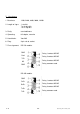
5. Examples for potential responses to control or write commands resp. to command telegrams with data (format) errors: 1. Analyzer and/or system unit with several analyzers "Online" and called analyzers are existing. 1. Byte STX 2. Byte DON'T CARE 3. Byte C 4. Byte O 5. Byte D 6. Byte E 7. Byte BLANK 8. Byte x Error status byte evtl. variable ... . ... Data n. Byte ETX Error status byte: 1 - 10 Value is zero: Value is not zero: Device without error. Device with one or more errors.
I) V24/RS232/485-Interface - Basics 2. Analyzer and/or system unit with several analyzers "Offline" and called analyzers are existing. 1. Byte STX 2. Byte DON'T CARE 3. Byte C 4. Byte O 5. Byte D 6. Byte E 7. Byte BLANK 8. Byte x 9. Byte BLANK 10. Byte K 11. Byte n 12. Byte BLANK 13. Byte O 14. Byte F Error status byte evtl. variable ... . ... Data n. Byte ETX Error status byte: 11. Byte: 90003752(1) [AK-Commands] 10/98 Value is zero: Device without error.
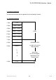
3. Called system unit "online", called single analyzer not available. If the test bench control computer will call the devices directly and the system unit or the analyzer are not available, you will not get any response telegram. So, the test bench control computer will have to realize the missing of the system or of the analyzer by "Time Out". 1. Byte STX 2. Byte DON'T CARE 3. Byte C 4. Byte O 5. Byte D 6. Byte E 7. Byte BLANK 8. Byte x 9. Byte BLANK 10. Byte K 11. Byte n 12.
I) V24/RS232/485-Interface - Basics 4. Called system unit "offline", called single analyzer not available. If the test bench control computer will call the devices directly and the system unit or the analyzer are not available, you will not get any response telegram. So, the test bench control computer will have to realize the missing of the system or of the analyzer by "Time Out". 1. Byte STX 2. Byte DON'T CARE 3. Byte C 4. Byte O 5. Byte D 6. Byte E 7. Byte BLANK 8. Byte x 9.
Error status byte: Value is zero: Value is not zero: 11. Byte: Channel number zero: "System unit offline" 17. Byte: Channel number one to n: "Called device not available. 1 - 14 Device without error. Device with one or more errors.
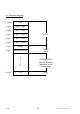
I) V24/RS232/485-Interface - Basics 5. Called unit or channel is busy with a running function. 1. Byte STX 2. Byte DON'T CARE 3. Byte C 4. Byte O 5. Byte D 6. Byte E 7. Byte BLANK 8. Byte x 9. Byte BLANK 10. Byte K 11. Byte n 12. Byte BLANK 13. Byte B 14. Byte S 15. Byte ETX Error status byte Error status byte: Value is zero: Value is not zero: 11. Byte: Channel number is zero: "The whole unit is busy". Channel number is one to n: "Single analyzer is busy".
6. The data are incomplete or the data do not have the expected format. 1. Byte STX 2. Byte DON'T CARE 3. Byte C 4. Byte O 5. Byte D 6. Byte E 7. Byte BLANK 8. Byte x 9. Byte BLANK 10. Byte K 11. Byte n 12. Byte BLANK 13. Byte S 14. Byte E 15. Byte ETX Error status byte: 1 - 16 Error status byte Value is zero: Value is not zero: Device without error. Device with one or more errors.
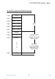
I) V24/RS232/485-Interface - Basics 7. The data or the parameters do not have the expected size. 1. Byte STX 2. Byte DON'T CARE 3. Byte C 4. Byte O 5. Byte D 6. Byte E 7. Byte BLANK 8. Byte x 9. Byte BLANK 10. Byte K 11. Byte n 12. Byte BLANK 13. Byte D 14. Byte F 15. Byte ETX Error status byte: 90003752(1) [AK-Commands] 10/98 Error status byte Value is zero: Value is not zero: Device without error. Device with one or more errors.
6. Function sequence and error status after the receipt of the 'SRES' or 'STBY' commands 1. The test bench control computer is sending the control command SRES (Reset) to the system unit or any single analyzer. All running functions or procedures will be canceled. An initializing will start, that is analogous to the switching on of the system unit or the analyzer: CPU and memory check, regulating or controlling of required temperatures, igniting of the flame in a FID an so on.
I) V24/RS232/485-Interface - Basics 2. The test bench control computer is sending the control command STBY (Standby) to the system unit or any single analyzer. There are two different cases: A If the system or the analyzer is resting, this mode will be finished. Then, it will be tried to get the stand-by mode ready for an error free measurement. The system or the analyzer will regulate all temperatures to the required setpoints, that were down during the resting.
B The system or the analyzer is in the operation mode SXYZ. This mode will be finished. Then, it will be tried to get the stand-by mode ready for an error free measurement. If there will be an error in the function SXYZ, the system or the analyzer will try to remove this error to get the stand-by mode ready for an error free measurement (i.e. FID flame is not burning, the FID will try to ignite).
II) V24/RS232/485 Interface - Single Analyzers and Systems Specifications of the criterions and codes for the communication between • the front-end computer (system computer) of an exhaust analyzer system and the test • • • • • bench control computer. each analyzer of an exhaust analyzer system and the test bench control computer. the front-end computer (system computer) of an exhaust analyzer system and their single devices.
1. Basic Informations You can distinguish three cases: (1) Exhaust analyzer system: Some analyzers are combined logically. That means, these analyzers are connected with the TBCC via an front-end computer (system computer). The communication does not take place directly between the TBCC and the analyzers, but it will take place via the frontend computer. The identification of each device resp. of the whole system will be done by a channel number.
II) V24/RS232/485 Interface - Single Analyzers and Systems The codes determined in this manual are valid for the communication between • the TBCC and the front-end computer of an exhaust analyzer system. • the front-end computer of an exhaust analyzer system and the corresponding single devices. • the TBCC and the single exhaust analyzers connected directly to the TBCC. • the TBCC and other exhaust measuring or analyzing devices or equipments connected directly to the TBCC.
If it is possible in a system to put single channels together to lines, so the following definition will be valid: A line is the summary of "1-x" analyzers to a logical group "y", that can be switched physically to a gas channel "z". Each device can only be assigned to one line at the same time. If you will try to assign a channel to another line and this channel is already assigned, the front-end computer will send as response "DF" (data error).
II) V24/RS232/485 Interface - Single Analyzers and Systems 2. List of all Codes 2.1. Control commands CODE SALI SARA SARE SATK Kn Kn Kn Kn SEGA SEMB SFRZ SGTS SHDA SHDE SINT SLCH SLIN Kn Kn Kn Kn K0 K0 Kn Kn Kn SLST SMAN SMGA SNAB SNGA SPAB SPAU Kn Kn Kn Kn Kn Kn Kn SQEF SREM SRES SROF Kn Kn Kn Kn SRON SSPL ST9O STBY Kn Kn Kn Kn Mm Mm Mm Mm Mm Function Page Linearization check with spangas Autoranging "OFF" (located range will remain) Autoranging "ON" Autom.
2.2.
II) V24/RS232/485 Interface - Single Analyzers and Systems 2.3.
3. Description of all Control Commands SALI – Control command "Linearization check with spangas" Starting this command the analyzer in a system or the single analyzer will start the spangas flow with all available spangases one after another. It will check the setpoint values automatically. The device will record the determined values and store the raw/ setpoint deviations. These deviations can be read with the command "AALI".
II) V24/RS232/485 Interface - Single Analyzers and Systems SARA – Control command "Autoranging OFF" SARE – Control command "Autoranging ON" Starting the command "Autoranging ON" the analyzers in a system or the single analyzer will select the best range for the current concentration automatically. With the control command "SEMB" the autoranging will be stopped and the range sent with the "SEMB" command will be selected. The command "Autoranging OFF" will stop this function, but the found range will remain.
SATK – Control command "Automatic calibration" Starting this command the analyzers in a system or the single analyzer will start a calibration procedure to determine the correction values. The required calibration gases and the pumps will be switched on automatically. Then, the calibration procedure will start automatically. Such a procedure has to run until the end. It may not be canceled or interrupted by other functions.
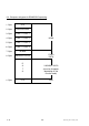
II) V24/RS232/485 Interface - Single Analyzers and Systems Stability control procedure Parameters: Wait dead time Tt, if gases were switched To Tt Start timer for time-out To Time-out [xx s] (max. time for stability control) Dead time [xx s] (Wait after gas switching) Ti Integration time [xx,x s] (for K1, Knew) Ts Stability time [xx s] Tol.
Stability control Begin of gas flow Begin of stability control New begin of stability control Signal = Knew Knew Knew K1 2 * Deviation K1 Ti Stability time Ts Dead time Tt Time-out Stability controlled procedure of the zero/span calibration Begin of the function SATK Average over Ti, Read with AANG Average over Ti, Read with AAEG Calibration Ti Ti Calibration Dead time 2 - 12 Stability time Stability time Dead time AK Stability time Stability time 90003752(1) [AK-Commands] 10/98
II) V24/RS232/485 Interface - Single Analyzers and Systems Only for platform: SCAL – Control command "Start system calibration" To control the system calibration procedures the commands "SCAL", "STBY" and "ASTZ" have to be used. With "SCAL" the procedures will be started. For more exact description of procedures see also the "documentation of system calibration". Starting condition: All attached analyzer module are in the stand-by mode ("AK STBY") and the variable "CALSTAT" is "0".
Stop command STBY K0 Function associated to the whole system unit Code Only using the channel number 0 (K0) will stop running "SYSCAL" procedure. Besides, all procedures of the other analyzer modules will be stopped. Response SCAL 0 Error status Code Read command ASTZ K0 Read of the whole FU Code With the command "ASTZ K0" it will be checked, if a system calibration is running or not. "SCAL" will be sent back for a running system calibration. If no system calibration is running this string will be missed.
II) V24/RS232/485 Interface - Single Analyzers and Systems SEGA – Control command "Spangas" Starting this command the analyzers in a system or the single analyzer will switch on the calibration valve to spangas and switch on the required pumps. This function will only check the end point. It will not correct the calibration. If continuous line recorders will be available, the paper transport will also be switched on.
SEMB – Control command "Set range" Starting this command the analyzers in a system or the single analyzer will set the range that is named in the data. If the function "Autoranging" is running at that moment, it will be stopped and the named range will be selected.
II) V24/RS232/485 Interface - Single Analyzers and Systems Only for CLD module: SENO/SNOX – Control command "Operation mode CLD" Starting the command "SENO" the CLD analyzers in a system or the single CLD analyzer will start the NO measurement. The command "SNOX" will start the NOx measurement.
SFRZ – Control command "Decimal point setup for floating point format" With this command the number of digits for real numbers will be setup. The real numbers will be set to the number of relevant digits. Standard setup: 6 relevant digits This command will have an effect to the output of all real numbers. It is not possible to vary it for different channels. Control command SFRZ K0 n n = 2, ...
II) V24/RS232/485 Interface - Single Analyzers and Systems SGTS – Control command "Device test" Starting this command the analyzers in a system or the single analyzer will switch off the calibration gas and the samplegas. That means, all gas tubes to the analyzer device will be closed and the pumps will be switched off. Then, the device can be checked via a gas input that is located directly in front of the device.
SHDE – Control command "Hold status ON" SHDA – Control command "Hold status OFF" We have the possibility to activate the "Hold"-feature not only per calibration. We can do this also by AK-Command "SHDE". With the command "SHDA" we have the possibility to deactivate an activated "Hold" again. Starting the command "SHDE" will switch on the "hold status". So it is possible to start the "Hold"-feature directly by AK command and not only per calibration.
II) V24/RS232/485 Interface - Single Analyzers and Systems SINT – Control command "Integrator" Starting this command the FU will activate the internal integrators. The previous calculated and stored integral averages will be set to zero. The integrator will calculate new integral averages as long as the control command "SINT" will be received again. The result of the integrator can be read with the command "AIKG".
SLCH – Control command "Linearization check" Starting this command the analyzers in a system or the single analyzer will switch on the gas tubing to a gas distribution and a linearization procedure will run. The device will record the correction values to the receiver specific raw curve. The deviations to the correction values of the last determined linearization will be stored. Look at the command "SLIN" for informations about the logic of the device control and of the gas distribution control.
II) V24/RS232/485 Interface - Single Analyzers and Systems SLIN – Control command "Linearization" Starting this command the analyzers in a system or the single analyzer will switch on the gas tubing to a gas distribution. A linearization procedure for the selected range will run. The device will record the determined correction values to the receiver specific raw curve. The values will be stored in the device to calculate the gas concentration.
SLST – Control command "Set linearization step" Starting this command the gas distribution will switch on the named distribution step. The device will work like described for the commands "SLIN" or "SLCH" depending on the current procedure. The device will only accept the "SLST" command, if the commands "SLIN" or "SLCH" were received before followed by the command "ELST".
II) V24/RS232/485 Interface - Single Analyzers and Systems SMAN – Control command "Operation mode MANUAL" With this command the FU will change to the operation mode "Manual". Then it will only be possible to start functions from an operating unit integrated in the FU. The same operation mode will be enabled, if the service switch of the FU will be in the position "Remote Disable". In that mode it will only be possible to answer to read commands of the TBCC.
SMGA – Control command "Samplegas" Starting this command the analyzers in a system or the single analyzer will switch on the sample gas valve and the pumps necessary for the samplegas transport. If continuous line recorders will be available, the paper transport will also be switched on.
II) V24/RS232/485 Interface - Single Analyzers and Systems SNAB – Control command "Zerogas calibration" Starting this command the analyzers in a system or the single analyzer will start a zerogas calibration. The calibration gas flow will start automatically and the calibration procedure will run. After this procedure will be over the system, the analyzer in a system or the single analyzer will change to the stand-by mode. The running calibration procedure can be canceled with the "STBY" command.
SNGA – Control command "Zerogas" Starting this command the analyzers in a system or the single analyzer will switch on the zerogas valve and the pumps necessary for the zerogas transport. This function will only check the zero point. It will not correct the calibration. If continuous line recorders will be available, the paper transport will also be switched on.
II) V24/RS232/485 Interface - Single Analyzers and Systems SPAB – Control command "Spangas calibration" Starting this command the analyzers in a system or the single analyzer will start a spangas calibration. The calibration gas flow will start automatically and the calibration procedure will run. After this procedure will be over the system, the analyzer in a system or the single analyzer will change to the stand-by mode. The running calibration procedure can be canceled with the "STBY" command.
SPAU – Control command "Pause" With this command the FU will be set to a defined status of interruption. This command will only be accepted, if the FU is already in the stand-by mode. The "SPAU" command will switch off the operation modes (e.g. FID flame, pump of an NO device) or the corresponding setpoints (e.g. temperature of the hot pipe). With the control command „Reset“ or „Stand-by“ the FU will change to the stand-by mode to get ready for operation.
II) V24/RS232/485 Interface - Single Analyzers and Systems SQEF – Control command "Cross interference" Starting this command the CO analyzer will measure wet C02. It will be produced by streaming three percent C02 through water bottles at 20 degrees Celsius. The CO analyzer will measure this gas mixture. The signal will be stored in the analyzer. It can be read by the TBCC with the "AQEF" command. The measured concentration has to be maximum 3 ppm for ranges smaller than 300 ppm.
SREM – Control command "Remote" With this command the FU will change to the computing operation mode. Then, the function start will only be possible by the TBCC. This operation mode may only be set, if the service switch of the FU is in the position "Remote Enable".
II) V24/RS232/485 Interface - Single Analyzers and Systems SRES – Control command "Reset" With this command the FU will get a software reset. This command has the same effect to the FU like the switching off and on of the power supply. All running procedures will be canceled. An initializing will be started, e.g. check and control of temperature setpoints. After that the operation modes "Manual" and "Stand-by" will be enabled.
SRON – Control command "Delay modus ON" SROF – Control command "Delay modus OFF" Starting this command the analyzers in a system or the single analyzer will determine measurement and integral values (averages), that will be delayed according to the delay time of the write command "EVEZ". The read commands "AKON", "AIKO" and "AIKG" will get an old value according to the synchronization time of the command "EVEZ". The analog output will get the same delay.
II) V24/RS232/485 Interface - Single Analyzers and Systems SSPL – Control command "Purging" Starting this command the analyzers in a system or the single analyzer will switch on the purge gas valve and the pumps necessary for the purge gas transport. This function can be finished either by a new command or by a defined time interval. After the purging will be over the system, the analyzer in a system or the single analyzer will change to the stand-by mode.
ST9O – Control command "Set t90 time step" With this command the analyzer will use the t90 time according to the current step. The abbreviation "S" means fast time, "M" means medium time and "L" means slow time. After the switching on of the device or after a "Reset" the fastest time will be set.
II) V24/RS232/485 Interface - Single Analyzers and Systems STBY – Control command "Stand-by" With the command "Stand-by" the FU will be set to a defined status of interruption. Running functions like measuring or purging will be canceled. Then, the stand-by mode will be enabled. The ranges will keep selected. The FU will get ready for measurement and operating, no matter which mode was the previous.
2 - 38 AK 90003752(1) [AK-Commands] 10/98
II) V24/RS232/485 Interface - Single Analyzers and Systems 4. Description of all Read Commands AAEG – Read command "Deviation to spangas" To this read command the analyzers in a system or the single analyzer will send to the TBCC the following data for the called channel (device): ∗ The measured and stored signal of the last spangas measurement. ∗ The deviation from the setpoint value of the linearized curve in ppm and percent, referred to the end of range value.
AALI – Read command "Deviations of the last linearization check with spangas" To this read command the analyzers in a system or the single analyzer will send to the TBCC the following data for the called channel (device) and subchannel (range): ∗ The determined and stored deviations in ppm of the last linearization check with spangas. Read command AALI Kn Mx Read of channel n and range x Code Response AALI 0 AAA BBB ......
II) V24/RS232/485 Interface - Single Analyzers and Systems AANG – Read command "Deviation to zerogas" To this read command the analyzers in a system or the single analyzer will send to the TBCC the following data for the called channel (device): ∗ The determined and stored signal of the last zerogas measurement with its range. ∗ The deviation from the setpoint value of the linearized curve in ppm and percent, referred to the end of range value.
ABST – Read command "Counter of operating hours" To this read command the FU will send to the TBCC the following data: ∗ The operating hours until now for the roots fan, the turbo compressor, the sampling pumps etc. The operating hours will only be sent as integers. Read command ABST K0 Read of the whole system unit Code Response ABST 0 T1 T2 ...
II) V24/RS232/485 Interface - Single Analyzers and Systems ADRU – Read command "Pressure" To this read command the analyzers in a system or the single analyzer will send to the TBCC the following data for the called channel (device) and if need be for the subchannel (pressure measurement): ∗ The signal in Pascal. Note: At the moment no subchannels will be used.
ADUF – Read command "Flow" To this read command the analyzers in a system or the single analyzer will send to the TBCC the following data for the called channel (device) and subchannel (flow measurement): ∗ The signal in liter per time unit.
II) V24/RS232/485 Interface - Single Analyzers and Systems AEMB – Read command "Selected range" To this read command the analyzers in a system or the single analyzer will send to the TBCC the following data for the called channel (device): ∗ The selected and used range at this moment.
AFDA – Read command "Function length" To this read command the FU will send to the TBCC the following data for the called channel (device): ∗ The function or procedure times of the function determined in "CODE". Functions like "SATK", "SLIN", "SLCH", "SALI", "SQEF", "SNGA" or "SEGA" will run time controlled according to the times T1 to T4 or stability controlled. Time control: If only T1 is set or if T2 = 0, time control will run with step time T1 (total function time).
II) V24/RS232/485 Interface - Single Analyzers and Systems AGID – Read command "Device identification" To this read command the gas analyzer will send to the TBCC a text string consisting of several data. These data will be separated by a slash ( / ).
AGRW – Read command "Limits" To this read command the analyzers in a system or the single analyzer will send to the TBCC the following data for the called channel (device): ∗ The corresponding limits, e.g. maximum deviations of calibration.
II) V24/RS232/485 Interface - Single Analyzers and Systems AIKG – Read command "Concentration integral value; all" To this read command the FU will send to the TBCC the following data: ∗ The corrected average signal valid at that moment (e.g. analyzed value), that has been calculated since the last "SINT" command. The physical parameter is described in the section about FU.
Response AIKG 0 123400 12340 1234 123.4 12.34 -1.23 # Channel 7 no signal, invalid or range overflow/underflow Channel 6 negative value 1 digit before/ 2 digits after decimal point. Channel 5 positive value 2 digit before / 2 digits after decimal point. Channel 4 positive value 3 digits before / 1 digit after decimal point.
II) V24/RS232/485 Interface - Single Analyzers and Systems AIKO – Read command "Concentration integral value" To this read command the FU will send to the TBCC the following data: ∗ The corrected average signal valid at that moment (e.g. analyzed value), that has been calculated since the last "SINT" command resp. the last "AIKO" command. The physical parameter is described in the section about FU.
Response AIKO 0 123400 12340 1234 123.4 12.34 -1.23 # Channel 7 no signal, invalid or range overflow/underflow Channel 6 negative value 1 digit before/ 2 digits after decimal point. Channel 5 positive value 2 digit before / 2 digits after decimal point. Channel 4 positive value 3 digits before / 1 digit after decimal point.
II) V24/RS232/485 Interface - Single Analyzers and Systems AKAK – Read command "Calibration gas concentration" To this read command the analyzers in a system or the single analyzer will send to the TBCC the following data for the called channel (device) and range: ∗ The calibration gas concentration in ppm. Read command AKAK Kn [Mx] Range number (optional); x = 1, 2, 3, 4 Output of all ranges, if no range is named. Read of channel n Code Response AKAK 0 M1 XXX M2 XXX ...
AKAL – Read command "Stored calibration corrections" To this read command the analyzers in a system or the single analyzer will send to the TBCC the following data for the called channel (device): ∗ The corrections in ppm determined and stored during the last calibration. These corrections are also necessary to calculate the analyzer values (deviations from the linearized curve).
II) V24/RS232/485 Interface - Single Analyzers and Systems Response AKAL 0 M1 aaa kk AAA KK .....
AKEN – Read command "Device tag" To this read command the FU will send to the TBCC the tag for the called channel (device). Read command AKEN K0 AKEN Kn Read of channel n Code Response AKEN 0 XXX..
II) V24/RS232/485 Interface - Single Analyzers and Systems AKFG – Read command "Configuration of the system" To this read command the system will send to the TBCC the following data: ∗ The adjustment about the channels (analyzers or virtual channels) that are expected to send the current signals and the corresponding sequence. ∗ The channels that can be called with the total channel command "K0".
AKON – Read command "Signal" (measured concentration value) To this read command the analyzers in a system or the single analyzer will send to the TBCC the following data: ∗ The corrected signal (concentration value) valid at that moment. Normally the physical unit is ppm. The value will be limited to six relevant digits, because it is useless to send gas concentrations in an accuracy less than pars pro mille. Example for four relevant digits (default: six digits): measured conc. [ppm] sent conc.
II) V24/RS232/485 Interface - Single Analyzers and Systems Response AKON 0 123400 12340 1234 123.4 12.34 -1.23 # Channel 7 no signal, invalid or range overflow/underflow Channel 6 negative value 1 digit before/ 2 digits after decimal point. Channel 5 positive value 2 digit before / 2 digits after decimal point. Channel 4 positive value 3 digits before / 1 digit after decimal point.
AKOW – Read command "Correction for zerogas calibration and gradient" To this read command each analyzer in a system or the single analyzer will send to the TBCC the following data: ∗ The correction of the last zero calibration and the gradient of the calibration curve.
II) V24/RS232/485 Interface - Single Analyzers and Systems ALCH – Read command "Deviations of the last linearization check" To this read command the analyzers in a system or the single analyzer will send to the TBCC the following data for the called channel (device) and subchannel (range): ∗ The determined and stored deviations of the last linearization check in ppm. ∗ The information if these deviations will be in the lawful tolerances. That means: Is the check o.k.
Only for MLT analyzers: ALIK – Read command "Output of the linearization curve" To this read command the x/y values of the linearization curve will be sent. With this values can be determined the desired segment of the linearization curve and the interval between the function values. Read command ALIK Kn a b c Interval between the function values [ppm] End concentration of the segment [ppm] Beginning concentration of the segment [ppm] Read of channel n Only one channel can be checked (no K0).
II) V24/RS232/485 Interface - Single Analyzers and Systems ALIN – Read command "Linearization values" (X/Y = Setpoint / Raw value) To this read command the analyzers in a system or the single analyzer will send to the TBCC the following data for the called channel (device) and subchannel (range): ∗ The determined and stored setpoint/raw values of the last linearization. Read command ALIN Kn [Mx] This information is optional. It will not be evaluated, because the values are valid for all ranges.
ALKO – Read command "Polynomial coefficients of the linearization curve" The coefficients of the linearization polynomial calculated by the analyzer linearization will be transferred. These coefficients will be enabled using the polynomial method to linearize. Read command ALKO Kn Mm Read of channel n and range m Code Response ALKO 0 Mm a0 a1 a2 a3...
II) V24/RS232/485 Interface - Single Analyzers and Systems ALST – Read command "Linearization steps" To this read command the gas distribution will send to the TBCC or to the system the following data: ∗ The numbers and the division in percent of the distribution steps (maximum two digits after decimal point). This command will only be accepted by the gas distribution, if the commands "SLIN" or "SLCH" have been received before.
AM90 – Read command "Actual response time (t90)" To this read command the analyzer will send the t90 time in seconds that is enabled to calculate the concentration for the called channel at the moment. Cf.
II) V24/RS232/485 Interface - Single Analyzers and Systems AMBA – Read command "Begin of range" To this read command the analyzers in a system or the single analyzer will send to the TBCC the following data for the called channel (device): ∗ The begin of range values in ppm. Read command AMBA K0 [Mx] AMBA Kn [Mx] Range number (optional) Read of channel n Code Response AMBA 0 Mx XXX Begin of range x Range No. x Error status Code The values will get the same format for the read of single channels.
AMBE – Read command "End of range" To this read command the analyzers in a system or the single analyzer will send to the TBCC the following data for the called channel (device): ∗ The end of range values in ppm. Read command AMBE K0 [Mx] AMBE Kn [Mx] Range number (optional) Read of channel n Code Response AMBE 0 Mx XXX End of range x Range No. x Error status Code The values will get the same format for the read of single channels.
II) V24/RS232/485 Interface - Single Analyzers and Systems AMBU – Read command "Switching values for autoranging" To this read command the analyzers in a system or the single analyzer will send to the TBCC the following data for the called channel (device): ∗ The adjusted switching values in ppm for a changing of ranges with autoranging. Read command AMBU K0 AMBU Kn Read of channel n Code Response AMBU 0 M1 xxx XXX M2 yyy YYY Mn zzz ZZZ Switch on value of range n Switch off value of range n Range No.
AMDR – Read command "Manual adjusted pressure" To this read command the gas analyzer will send the value adjusted for the parameter. This value will be useful, if no pressure measurement will be installed in the analyzer. Read command AMDR Kn Read of channel n Code Response AMDR 0 a Pressure [Pa] Error status Code The values will get the same format for the read of single channels.
II) V24/RS232/485 Interface - Single Analyzers and Systems AQEF – Read command "Cross interference" To this read command the CO analyzer or the system will send to the TBCC: ∗ The concentration value in ppm determined and stored in the analyzer. This value will be stored in the device until a new cross interference will be determined by the "SQEF" command. The TBCC will control, if limits will be exceeded. The TBCC will also start actions if necessary.
ASOL – Read command "Setpoint value with limits" To this read command the FU will send to the TBCC the following data for the called channel (FU) and subchannel (e.g. heating): ∗ The adjusted setpoints with deviation limits for error reports. For the actual used devices subchannel "m" will be: m=0 m=1 m=2 m=3 m=4 m=5 m=6 m=7 Concentration Temperature Pressure Flow Pocket calculator No. 1 Pocket calculator No. 2 Pocket calculator No. 3 Pocket calculator No.
II) V24/RS232/485 Interface - Single Analyzers and Systems ASTA – Read command "General status of the system" To this read command the FU will send to the TBCC: ∗ All channels of the FU with any error in their status at that moment. A detailed description of the errors will not be sent to this read command. It is only possible to read channel No. 0.
ASTF – Read command "Error status" To this read command the FU will send to the TBCC: ∗ All error existing at that moment in the called channel (FU). The description of the error characterization is specific for each device. It will be symbolized with a number. A reading to "K0" will get the errors of devices that are not assigned to single channels (e.g. samplegas cooler). Read command ASTF Kn Read of channel n Code Response ASTF 7 XXX YYY ...
II) V24/RS232/485 Interface - Single Analyzers and Systems TTypical meanings of errors for certain devices: NDIR/NDUV Analyzers No. 1 = Flow error No. 2 = Chopper failure No. 3 = Thermostat failure No. 4 = RAM error No. 5 = Calibration error zerogas No. 6 = Calibration error spangas No. 7 = Range overflow No. 8 = External error (digital input) No. 9 = Error of pressure measurement No.10 = Error of temperature measurement TFID Analyzers No. 1 = Flow error No. 2 = Flame out No. 3 = Thermostat failure No.
ASTZ – Read command "Status" To this read command the FU will send to the TBCC the following data for the called channel (FU): ∗ The device status at that moment ∗ Running procedures. The status will be described by the code used for the activation of the function. The operation modes "REMOTE" or "MANUAL" will also be sent. These modes will always be the first codes in the data string. To the read of channel 0 the statuses of all channels (FU) defined with "EKFG" will be sent.
II) V24/RS232/485 Interface - Single Analyzers and Systems Response ASTZ 0 KV SREM CODEn K1 SREM CODEn K2 # Kn SREM CODEn SMAN SMAN SMAN Status code Channel n and its status Device is not available Channel 2 and its status Status code Channel 1 and its status Status code Channel 0 and its status Error status Code ASTZ 0 Kn SREM CODEn SMAN Status code Channel n and its status Error status Code 90003752(1) [AK-Commands] 10/98 AK 2 - 77
ASYZ – Read command "System time" To this read command the FU will send to the TBCC the following data for the called channel (device): ∗ The current system time (calendar time).
II) V24/RS232/485 Interface - Single Analyzers and Systems AT9O – Read command "T90 time" (response time) To this read command the analyzers in a system or the single analyzer will send to the TBCC the following data for the called channel (device): ∗ The t90 time steps.
ATEM Read command "Temperature" To this read command the analyzers in a system or the single analyzer will send to the TBCC the following data for the called channel (device) and subchannel (temperature measurement): ∗ The signal in Kelvin. Read command ATEM K0 (m) ATEM Kn (m) Read of channel n (and subchannel m). Note: Subchannel m is not in use at the moment.
II) V24/RS232/485 Interface - Single Analyzers and Systems ATOL – Read command "Stability tolerances" To this read command the analyzers in a system, the single analyzer or the front-end computer will send to the TBCC the following data: ∗ The necessary tolerances for functions running stability controlled.
AUKA – Read command "Uncorrected analog value" To this read command the called analyzer in a system or the single analyzer will send to the TBCC the following data: ∗ The uncorrected analog output value in Volt and the corresponding range.
II) V24/RS232/485 Interface - Single Analyzers and Systems AVEZ – Read command "Delay and synchronization time" To this read command the analyzers in a system or the single analyzer will send to the TBCC the following data for the called channel (device): ∗ The delay time used for the record of valid signals or used to start the integrators by "SINT". ∗ The synchronization time used for the output of values from an internal buffer that were read by "AKON", "AIKO" and "AIKG".
AZEI – Read command "Times" To this read command the FU will send to the TBCC the following data for the called channel (FU): ∗ The times used to start a function or procedure, e.g. times for the automatic start of a calibration.
II) V24/RS232/485 Interface - Single Analyzers and Systems 5. Description of all Write Commands EFDA – Write command "Function length" With this write command the FU will get the function length of the function "SXXX" in seconds for the called channel (device), e.g. "Time Out" for purging or for switching on the calibration gases. If the function "SXXX" will be a procedure with several internal steps, the times will be valid for each step and not for the whole procedure.
Response EFDA 0 Error status Code 2 - 86 AK 90003752(1) [AK-Commands] 10/98
II) V24/RS232/485 Interface - Single Analyzers and Systems EGRW – Write command "Limit" With this write command the analyzers in a system or the single analyzer will get the required limits for the called channel (device), e.g. maximum deviation for calibration. If these limits will be exceeded during the operation, it will cause a changing of the error status byte. – The unit of limits is percent. The deviation value is referred to the setpoint.
EKAK – Write command "Calibration gas concentration" With this write command the analyzers in a system or the single analyzer will get the spangas values for each range. Write command EKAK K0 M1 YYYY ... Mx ZZZZ EKAK Kn M1 YYYY ...
II) V24/RS232/485 Interface - Single Analyzers and Systems EKEN – Write command "Device tag" With this write command the FU will get a tag to store in the FU memory. Then it will have to be unchangeable. That means, if this part of memory will be written, the device processor will have to save it against an overwriting automatically. The setup of a new tag will only be possible by changing the processor. The memory size for the tag is 30 ASCII characters.
EKFG – Write command "Configuration of the system" With this write command the FU will get the channels (analyzers) sending the current signals and their sequence. Furthermore the FU will get the channels that should be called with the total channel command "K0" or "KV Ln", i.e. the channels that shall be included to operation modes like measurement, zerogas and spangas. With the string XYZ the FU will be told which chemical component or virtual device (e.g. Lambda) shall be combined with which channel.
II) V24/RS232/485 Interface - Single Analyzers and Systems ELIN – Write command "Linearization values (X/Y)" With this write command the analyzers in a system or the single analyzer will get the linearization values for the calculation of gas concentration for the called channel (device) and subchannel (range). A new linearization curve will be calculated with these x/y-pairs. Write command ELIN Kn Mx aaa AAA bbb BBB ...
ELKO – Write command "Polynomial coefficients of the linearization curve" The coefficients of a linearization polynomial will be transferred to the analyzer. These values will then be enabled to calculate the gas concentration using the polynomial method for linearization. Write command ELKO Kn a0 a1 a2 a3...
II) V24/RS232/485 Interface - Single Analyzers and Systems ELST – Write command "Linearization steps" With this write command the device will get the numbers of the distribution steps and each division in percent of the gas distribution used for linearization. But this command will only be accepted, if the commands "SLIN" or "SLCH" were received before. Write command ELST Kn 1 XY 2 XY ...
EMBA – Write command "Begin of range" With this write command the analyzers in a system or the single analyzer will get each begin of range of the total range in ppm. The analog output signal will be referred to these values for instance. Write command EMBA Kn M1 YYYY [...
II) V24/RS232/485 Interface - Single Analyzers and Systems EMBE – Write command "End of range" With this write command the analyzers in a system or the single analyzer will get each end of range of the total range in ppm. The analog output signal will be referred to these values for instance. Write command EMBE Kn M1 YYYY [...
EMBU – Write command "Switch levels for autoranging" With this write command the analyzers in a system or the single analyzer will get for the called channel (device): ∗ The required values in ppm to switch from one range to another with autoranging. Write command EMBU Kn Mn XXX YYY [Mm XXX YYY ...
II) V24/RS232/485 Interface - Single Analyzers and Systems EMDR – Write command "Manual adjusted pressure" With this write command the analyzer will get a pressure value for the called channel. This value will be used as pressure correction, if no pressure measurement is installed in the device. Cf.
ESOL – Write command "Setpoint value with limits" With this write command the FU will get the required setpoint values with acceptable deviations for the called channel (device) and subchannel (e.g. heating). If these limits will be exceeded during the operation, it will cause a changing of the error status byte. For the actual used devices subchannel "m" will be: m=0 m=1 m=2 m=3 m=4 m=5 m=6 m=7 Concentration Temperature Pressure Flow Pocket calculator No. 1 Pocket calculator No. 2 Pocket calculator No.
II) V24/RS232/485 Interface - Single Analyzers and Systems ESYZ – Write command "System time" With this write command the FU will get the system time (calendar time) that has to be adjusted for the called channel (device).
ET9O – Write command "T90 time" (response time) With this write command the analyzers in a system or the single analyzer will get the t90 time steps in seconds that have to be adjusted for the called channel (device).
II) V24/RS232/485 Interface - Single Analyzers and Systems ETOL – Write command "Stability tolerances" With this write command the analyzers in a system, the single analyzer or the front-end computer will get the required tolerances for functions running stability controlled. The tolerance will be specified in percent of the end of range value. The tolerance can be adjusted for each range separately. No tolerance check will be done, if the tolerance value will be set to T = 100%.
EVEZ – Write command "Delay and synchronization time" With this write command the analyzers in a system or the single analyzer will get the delay time and the synchronization time for the called channel (device). The delay time will be used for integrators started by "SINT" or for the delayed record of valid signals. The synchronization time will be used for the output of values that were read by "AKON", "AIKO" and "AIKG" from an internal buffer.
II) V24/RS232/485 Interface - Single Analyzers and Systems EZEI – Write command "Times" With this write command the FU will get the times that have to be adjusted in the called channel (device) for the automatic start of functions or procedures (e.g. "Automatic calibration"). Furthermore, the FU will get the function length in seconds. The following controls will be possible: • If the calendar day will be mentioned, the function will start only once at one date.
Write command EZEI Kn CODE JJMMTT hhmmss T-0 Function length Start time of the function Start day of the function Function that shall be started Addressed channel Code Response EZEI 0 Error status Code 2 - 104 AK 90003752(1) [AK-Commands] 10/98
Supplement 1. Overview about working AK commands in NGA devices Code Function MLT local V3.2 MLT/CU V3.
Code ELST EMBA EMBE EMBU EMDR EPAR ESOL ESYZ ET90 ETOL EVEZ EZEI SALI SARA SARE SATK SCAL SEGA SEMB SENO SFRZ SGTS SHDA SHDE SINT SLCH SLIN SLST SMAN SMGA SNAB SNGA SNOX SPAB SPAU SQEF SREM SRES SROF SRON SRUC SSPL ST90 STBY Function Linearization steps Begin of ranges End of ranges Switch levels for autorange Manual pressure value Parameters general Setpoints with limits Time and date of the system t90 times Tolerances for stability controlled procedures Delay and synchronization time Times for procedures
Supplement 2. AK Service Commands ASVC K0 S599 ExactNode Name Reading of LON variables of a network node Description: This command is an enlarged alternative to the S600 command. It may use the variables of all network nodes, even if they will not be analyzer modules. You only have to know the right node address (cf. S632). Syntax: ExactNode = Name = Right network node address Name of the variable Response: ASVC 0 a a: Value of the desired variable Notes: Cf.
S600: Access to LON network variables Access to network variables of an analyzer module. Notes: + If a variable will contain several values (array), you can access to these values by adding the corresponding number directly to the name of the variable. Example: LINYA = [31, 44, 54] LINYA1 = 31 LINYA2 = 44 LINYA3 = 54 + The network variable knows its data type. The AK command will try to convert the text of value inputs to the required type.
Supplement ASVC Kn S615 b Reading of the current data of a DIO board Description: The current status of the named DIO board will be read. Syntax: b: Board number (1, 2, 3 ,4; not SLOT-ID); for b = 0 the data of all available DIO's will be sent Response: ASVC 0 IIIIIIII OOOOOOOO OOOOOOOO OOOOOOOO RLLL I1...8 Status of the digital input pins 1...8 O1...24 Status of the digital output pins 1...24 R Retrigger error L1...3 Overload group 1...
SSVC Kn S621 a Loading/Saving of device specific parameters Description: With this command you can load/save the device specific parameters. This will be possible via the serial interface and from /to the internal FLASH memory (if on ACU available!). Syntax: a= Notes: The data format for the loading via the serial interface (a = 1) corresponds to the data format of the serial sending out (a = 2). not 1: 2: 3: 4: loading new configuration via the serial interface.
Supplement ASVC Kn S630 Description: All LON variables that are available in an analyzer module will be sent out with their names. If a variable will contain several values (array), it will be marked by an appendix in brackets. In these brackets you will find the numbers to access to the array values of the variable. Example: Notes: Output of the LON variable names LINYA[1-7] contains 7 values. You can access to these values with the names LINYA1, LINYA2, ... LINYA7. K0 is not possible.
ASVC Kn S640 a Output of values of the MLT concentration formula Concentration formula: Conce = FacP * FacT * FacSpan * Lin{(RawAvg - OffP - OffT - OffX) * RGain * Gain} Meaning of the variables: RawAvg: OffP: OffT: OffX: RGain: Gain: Lin: FacSpan: Raw value average (including t90 time) Offset correction of physics Offset correction of temperature Offset correction of interferences from other channels Analog pre amplifying factor (BIS) Factor standardizing to the desired setpoint value (span) Lineariza