
Brochures and Data Sheets
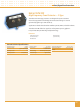
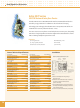

Edco PC642 Series
Zone/Loop/Data
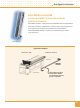
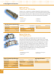
The Edco PC642 Series surge suppressor is a two-pair (four-wire) module
implementing three-stage hybrid technology. This module addresses
over-voltage transients with gas tubes and silicon avalanche components.
In addition, sneak and fault currents are mitigated with resettable fuses (PTCs).
The PTCs increase resistance several orders of magnitude when over-currents
exceed safe levels. A normal state resumes when over-currents are removed.
The ability to self-restore in this manner significantly increases suppressor
performance and survivability.
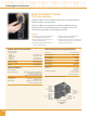
The Edco PC642 card edge module is gold-plated, double-sided, and is designed
to mate with the Edco PCB1B gold-plated female terminal connector. When
snapped together, the data circuits “pass thru” the protector in a serial fashion
from the four “Field Side” terminals to the four “Electronics Side” terminals.
Terminals 1 or 10 of the Edco PCB1B must be attached to Building-Approved
Ground per Edco Technical Bulletin # 2015.
Features
Three-stage hybrid protection
Sneak/fault current protection
Resettable fusing — PTCs
Low capacitance option
Plug-in module
Fast response time
Requires Edco PCB1B base
PC642PTU (Pass Thru Unit)
available for troubleshooting
5 year warranty
EDCO PCB1B BASE SOLD SEPARATELY
General Technical Specifications
Operating Voltage 5, 12, 18, 24, 30, 36,
43, 52, 180 VDC
Clamping Voltage 8, 15, 20, 30, 36, 43,
50, 60, 200 VDC
Operating Current 0.15 A
Peak Surge Current 10 kA (8 x 20 µs)
Frequency Range 0 to 20 MHz
Insertion Loss < 0.1 dB at 20 MHz
SPD Technology GDT, SAD, w/Series PTC
Connection Type Terminal block
w/compression lugs
Terminals accept up to 10 AWG
Operating Temperature -40°C to +85°C
Dimensions (Inches) 2H x 1W x 2.5L
(PC642 + PCB1B Base)
Weight 1 oz
Certifications UL 497B
Caution: The hybrid design of this product includes
series resistance. Do not place this product in service
on any signal line capable of supplying more than
150 milliamperes continuously.
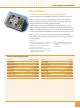
Terminal Assignments
PCB1B:
Unprotected Pair 2
Unprotected Pair 1
Protected Pair 2
Protected Pair 1
Keying Pin
Even TerminalsOdd Terminals
Field Side
Electronics Side
9
7
5
3
1
10
8
6
4
2
1.0
{
}
}
{
2.125"
2.4"
Groun d Terminal 1 or 10 to Build ing Approved Ground
DO NOT daisy chain grounds. NOT intended for shield
termination. Install ground in accordance with all
applicable codes.
Ordering Information
PC642
PCB1B
APPLICATION:
RS485, RS422: PC642C-008LC & PCB1B
RS423, Token Ring: PC642C-008LC & PCB1B
RS232: PC642C-020 & PCB1B
E-NET, 10 BASE T: PC642C-030LC & PCB1B
4–20ma: PC642C-036 & PCB1B
How to Specify the Appropriate Model
-
VOLTAGE CLAMP
60 Volts
50 Volts
43 Volts
36 Volts
30 Volts
15 Volts
8 Volts
2 0 0
PC642C
20 Volts
*200 Volts
0 6 0
0 5 0
0 4 3
0 3 0
0 2 0
0 3 6
0 1 5
0 0 8
no suffix
stage 2 clamp
each line-to-ground
stage 2 clamp
line-to-line only
stage 2 clamp line-to-line
and each line to ground
D
X
low capacitance option stage
2 clamp line-to-line and each
line to ground
•Not UL Listed
LC
20
Data/Signal Line Protection