
Installation Manual

AC Power
Connectivity
DC Power
Embedded Computing
Embedded Power
Industrial Power
Infrastructure Management & Monitoring
Outside Plant
Thermal Management
Racks and Integrated Cabinets
Power Switching & Controls
Services
Emerson Network Power.
The global leader in enabling
Business-Critical Continuity
TM
.
IO-50124 10/13 Rev. 3 Printed in USA
Business-Critical Continuity, Emerson Network Power and the Emerson Network Power
logo are trademarks and service marks of Emerson Electric Co. ©2013 Emerson Electric Co.
www.emersonnetworkpower.com/surge
Emerson Network Power Contact information
Headquarters
Surge Protection
100 Emerson Parkway
Binghamton, NY 13905
T: (607) 721-8840
T: (800) 288-6169
F: (607) 722-8713
E: SurgeTech@Emerson.com
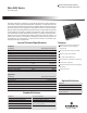
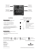
Installation
Ordering Information
Signal Line Connections:
• Connect GND Terminal to Local Ground
using #12 AWG wire minimum
• L1 and L2 – Connect for Signal Pair #1
• L3 and L4 – Connect for Signal Pair #2
• Terminals accept #24-#14 AWG wire,
torque to 4kg-cm
• “S” Connection for Cable Shield ( If Applicable )
CAUTION: Do not place this product in service on any
signal line capable of suppying more than 150
milliamperes continuously.
AC Power Connections:
• Connect AC Power as Marked on Case using
#12 AWG wire minimum
• Keep 120 VAC Power feed separate from Low Voltage
4/20 mA feed
UNPROTECTED
(FIELD) SIDE
4/20 mA SIGNAL
PROTECTED
(EQUIP) SIDE
4/20 mA SIGNAL
UNPROTECTED
(FIELD) SIDE
120 VAC POWER
PROTECTED
(EQUIP) SIDE
120 VAC POWER
1 = 0 No Enclosure
1 Polycarbonate Case (Standard)
2 Stainless Steel (Optional)
3 Fiberglass (Special)
2 = 0 Without PC642 Signal Protector
2 With PC642
3 = 036 PC642 Voltage Clamp Selection
043
*For Standard Unit order part # SLAC-12036
SLAC — 1 2 3 LC