
User Guide


Appendices.....79
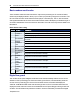
Command Description
detected, NO CARRIER will be reported instead of NO DIALTONE.
ATX2
Disables monitoring of busy tones. Sends only OK, CONNECT, RING, NO CARRIER, ERROR,
NO DIALTONE and CONNECT XXXX. If busy tone detection is enforced and busy tone is
detected, NO CARRIER, will be reported instead of BUSY. If dial tone detection is enforced or
selected and dial tone is not detected, NO CARRIER will be reported instead of NO DIALTONE.
ATX3
Enables monitoring of busy tones. Sends only OK, CONNECT, RING, NO CARRIER, ERROR,
NO DIALTONE and CONNECT or CARRIER XXXX. If dial tone detection is enforced and dial
tone is not detected, NO CARRIER will be reported.
ATX4 Enables monitoring of busy tones. Sends all messages (default).
ATZ0 Soft reset.
AT&C0 DCD remains on at all times.
AT&C1 DCD follows the state of the carrier (default).
AT&D0 Ignores DTR.
AT&D1 Enters the escape mode when ON-to-OFF transition is detected on DTR.
AT&D2
Hangs up, assumes command state and disables auto answer upon detecting ON-to-OFF
transition of DTR (default).
AT&D3
ON-to-OFF transition causes the modem to perform a soft reset. It is the same as if an ATZ
command is issued.
AT&F Restores factory configuration.
AT&G0 Disables guard tone (default).
AT&G1 Enables 550-Hz guard tone.
AT&G2 Enables 1800-Hz guard tone.
AT&K0 Disables flow control.
AT&K3 Enables RTS/CTS flow control (default for data modes).
AT&K4 Enables XON/XOFF flow control.
AT&K5 Supports transparent XON/XOFF flow control.
AT&P0 39/61 make/break ratio at 10 pulses per second (default).
AT&P1 33/67 make/break ratio at 10 pulses per second.
AT&P2 39/61 make/break ratio at 20 pulses per second.
AT&P3 33/67 make/break ratio at 20 pulses per second.
AT&Q0 Selects direct asynchronous operation.
AT&Q5 Modem will try an error-corrected link.
AT&Q6
Selects asynchronous operation in normal mode (allows speed buffering and flow control but no
error correction).
AT&V
Displays modem’s current configuration. When this command is entered, the modem will display
its current command and register settings.
AT%C0 Disables data compression.
AT%C1 Enables MNP 5 data compression.
AT%C2 Enables V.42 bis data compression (sets S46 bit 1).
AT%C3 Enables V.42 bis and MNP 5 data compression (default).
AT%E0 Disables line quality monitor and auto-retrain.
AT%E1 Enables line quality monitor and auto-retrain.
AT%E2 Enables line quality monitor and fallback/fall-forward (default).
AT%L Line signal level. Returns a value that indicates the received signal level. Example, 009 = -9dBM.