
User Guide


Installation.....9
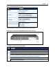
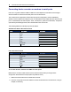
Label Description
PWR/CPU
• Blue Blinks - During unit boot
• Solid - During operation
• Off - Power is off
ETH 0/ETH 1
• Amber - Link at 10BaseT speed
• Yellow - Link at 100BaseT speed
• Green - Link at 1000BaseT speed
• Off - No link/cable disconnected/Ethernet fault
AUX/MODEM
Dual LED: Yellow on top, green on bottom
• Yellow - DTR/DCD activity
• Green - TXD and RXD activity
• Off - No activity
[One LED for each serial port]
Green
• Blinks - Ready, with activity
• Solid - Ready
• Off - Not ready
LEDs on the Console Server Front
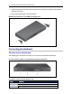
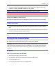
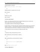
The following figure shows the rear connectors on the console server.
Rear of the Console Server (ACS 6032 Console Server Shown)
Number
Description
1 Power supplies (dual AC shown).
2 Serial ports (32 ports shown). Models come with 4, 8, 16, 32 or 48 serial ports.
3 ETH 1 10/100M/1G Ethernet port. Can be connected to a second network or used for failover.
4
AUX/Modem port. If an optional internal modem is ordered, this port is defined as a V.92 modem at
the factory; otherwise, the port is factory-defined as RS-232 with an RJ-45 ACS console server
pinout and can be used to connect either an external modem or a power device.
5 ETH0 10/100M/1G Ethernet port for remote IP access.
6
Console port. Allows for local administration and access to connected devices through a terminal or
a computer with a terminal emulator.
Connectors on the Console Server Rear