
Technical data


Guide Specifications for Liebert Mini-Mate2- 5-Ton Systems
40 Liebert
®
Mini-Mate2
™
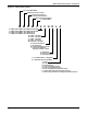
2.2 Direct Expansion System Evaporator Components
2.2.1 Direct Expansion Coil
The evaporator section shall include evaporator coil, thermostatic expansion valve and filter drier.
The evaporator coil shall have 5.6 sq.ft. (0.52 sq.m) face area, four rows deep. It shall be constructed of
copper tubes and aluminum fins and have a maximum face velocity of 444 FPM (2.26 m/s) at
2500 CFM (4248 CMH). An externally equalized thermostatic expansion valve shall control
refrigerant flow. The evaporator coil shall be factory-charged with R-407C refrigerant and sealed. The
evaporator unit can be coupled directly with the condensing unit or mounted remote to the
condensing unit.
The coil shall be provided with a condensate drain pan with an internally trapped drain line. The
evaporator drain pan shall include a factory-installed float switch to shut down the evaporator upon
high water condition.
2.2 Chilled Water System Components
2.2.1 Chilled Water Control Valve (On/Off)
The (2-way) (3-way) control valve shall be motorized slow-acting, non-spring return type to reduce
water hammer. Design pressure shall be 300psig (2067kPa) static pressure, with a maximum close-off
pressure of 60psi (414kPa).
2.2.2 Chilled Water Control Valve (Modulating)
A (2-way) (3-way) modulating, non-spring return valve controlled by the microprocessor to position
the valve in response to room conditions. Design pressure shall be 400psig (2758kPa) static pressure,
with a maximum close-off pressure of 72psi (496kPa).
2.2.3 Chilled Water Coil
The cooling coil shall have a minimum of 5.6 sq.ft. (0.52 sq.m) face area, 4 rows deep. It shall be
constructed of copper tubes and aluminum fins and have a maximum face velocity of 444 FPM (2.26
m/s) at 2500 CFM (4248 CMH). The coil shall be supplied with 45°F (7.2°C) entering water
temperature. The coil shall be supplied with ______ GPM (l/s) of chilled water and the pressure drop
shall not exceed ______ psi (kPa). The coil assembly shall be mounted in a condensate drain pan with
internally trapped drain line. The evaporator drain pan shall include a factory-installed float switch
to shut down the evaporator upon high water condition.
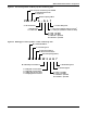
2.3 Indoor Air-Cooled Centrifugal Fan Condensing Unit
Condensing unit components shall include condenser coil, scroll compressor, high-pressure switch,
Liebert
Lee-Temp
™
refrigerant receiver, head pressure control valve, hot gas bypass system and
liquid line solenoid valve. The hot gas bypass circuit shall be provided to reduce compressor cycling
and improve operation under low load conditions.
All components shall be factory-assembled, charged with R-407C refrigerant and sealed. No internal
piping, brazing, dehydration or charging shall be required. Condensing unit shall be designed for
95°F (35°C) ambient and be capable of operation to -30°F (-34.4°C). The condensing unit can be
coupled directly to the evaporator or can be mounted remote to the evaporator.
The condenser coil shall be constructed of copper tubes and aluminum fins. The condenser fan shall
be centrifugal type, double inlet, heavy-duty steel shaft, with self-aligning bearings. The fan motor
shall operate at 1750 rpm (1450 rpm @ 50 Hz), shall be equipped with adjustable motor pulley, and
shall be mounted on an adjustable base. The fan and motor assembly shall be mounted on vibration
isolators. The fan motor assembly shall be belt-drive.
The condenser fan shall be designed for 3500 CFM (5947 CFH) at 0.5" (13mm) w.g. external static
pressure.