
Technical data

Chilled Water Systems—Capacities and Dimensions
Liebert
®
Mini-Mate2
™
23
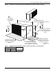
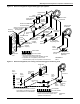
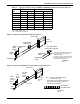
Figure 14 General arrangement, chilled water systems
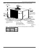
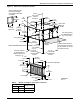
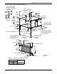
Figure 15 General arrangement, hot water reheat, chilled water units
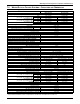
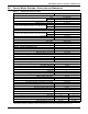
Table 12 Capacity correction factors for MMD91C & MMD92C based on 10°F (5.6°C) water rise
EWT
72°F (22.2°C) 50% RH 75°F (23.9°C) 45%RH
TCC SCC TCC SCC
42°F (5.6°C) 1.28 1.14 1.23 1.12
43°F (6.1°C) 1.18 1.09 1.14 1.07
44°F (6.7°C) 1.09 1.05 1.07 1.03
45°F (7.2°C) 1.00 1.00 1.00 1.00
46°F (7.8°C) 0.92 0.95 0.93 0.96
47°F (8.3°C) 0.85 0.90 0.87 0.92
48°F (8.9°C) 0.79 0.85 0.81 0.88
49°F (9.4°C) 0.73 0.79 0.77 0.82
EWT = Entering Water Temperature
TCC = Total Cooling Capacity
SCC = Sensible Cooling Capacity
Bleed Valve
Shutoff **
Valves
Chilled
Water Coil
Chilled Water
Control Valve
Chilled Water
Supply
Chilled
Water
Return
Hose Bibs**
3 - Way Chilled Water
Control Valve (Optional)
Chilled Water
Return
Chilled Water
Supply
DPN000215
Rev. 3
* Use Liebert sweat adapter kit with field
hard piping. Close-coupling option
available with MCD.
** Components are not supplied by Liebert
but are recommended for proper circuit
operation and maintenance.
DPN000219
Rev. 3
FIELD PIPING
Note: Hot water reheat available only
on chilled water units.
* Components are not supplied by Emerson
but are recommended for proper circuit
operation and maintenance.
Y-St raine r
Hot Water
Reheat
Coil
Bleed Valve
Hot Water
Reheat
Control
Valve
Water
Supply
To Un it
Water
Return
From Unit
Shutoff*
Valves
Hose*
Bibs
FACTORY PIPING