
Installation Manual
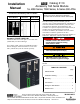

SERIAL MODULE INSTALLATION (continued)
3
label
DIP
switches
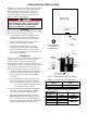
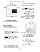
Figure 4. Termination resistor DIP switches on
bottom of Serial Module. Must be ON for ATS
farthest away from the h ost device.
Setting the ATS Address
Set the communication address in the ATS controller.
Follow either the 4000 & 7000 Series procedure or the
Series 300 procedure below. Use Table D to record the
address and other ATS information.
4000 & 7000 Series ATSs
1. R efer to Group 5 Controller User’s Guide
381333–126 pages 2–8 and 2–9 for how to set a
unique address for this A utoma tic Transfer Switch .
2. If ASCObus II protocol is used (such as used with
VPi computer software) and a Power Manager is
included with the ATS, the Power Manager must
be programmed with the same
addressasthat
selected for the ATS Group 5 Controller connected
to the Serial Module.
However, if ModbusprotocolisusedandaPower
Manager is included with the ATS, the PM must be
programm ed with a different and unique address
(not the same
as the address of the Controller).
For setting the address in Power Manager Xp refer
to Operator’s Manual 381333–199.
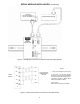
Series 300 ATSs
1. Remove the cover from the control ler by releasing
thelatchonrightsidewithyourthumb.SeeFigure5.
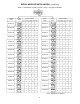
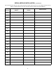
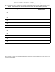
2. Locate DIP switc h S3 (left center) and set a unique
addr es s for this ATS. Use a ball – p oin t pen (or sim ilar
pointed tool) to slide the switch actuators left or
righ t so that they match the illus tration next to the
setting (l eft=off, right=on ). Rechec k the setting. See
Figures 6 & 7, and refer to Table C on the next page.
3. R einstall the cover on the controller by hooking it on
the left side and latching the right side.
4. The Series 300 ATS Group 1 Controller uses
ASCObus II protocol. Therefore, if a Power Manager
is inc lud ed with the ATS, the PM must be prog ram –
med with the same
address as that sel ected for the
ATS Group 1 Control ler conn ected to the Serial
Modul e. Refer to Operator’s Manual 381333–199.
thumb
latch
cover
hook on
left side
Figure 5. Group 1 Controller cover latch.
S3 DIP
switch
Figure 6. Location of S3 DIP switch in
Group 1 Controller (Series 300 ATSs).
DIP
switch
SW3
actuator
onoff
(8 on each DIP switch)
Figure 7. Setting DIP switch actuators.