
Installation Manual
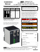

SERIAL MODULE INSTALLATION (continued)
2
SERIAL
MODULE
CAT.NO. 5110
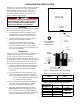
Optional Power Manager
Connect to
Group 5 Controller J7
Group 1 Controller J4
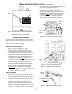
Figure 2. Serial Module connections to ATS Controller a nd Power Manager..
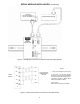
COM
TX –
TX +
RX –
RX +
SERIAL
MODULE
5
4
3
2
1
J4
shield
TX –
TX +
RX –
RX +
TO O THER ASCO
COMMUNICATION
DEVICES
NOTES:
1. Earth ground shield at host device only.
2. Field wiring: use UL Listed, stranded,
twisted pairs, overall foil shield with stranded
drain wire suitable for RS–422 equivalent to:.
(Standard 80 degrees C) Belden 9842 or
9829 or Alpha 6202C or 6222C.
(Plenum rated)
Belden 89729 or 82729 or Alpha 58902.
Figure 3. Serial communication connections to the Serial Module.