
Brochures and Data Sheets


4200–062 3 Revision 2.01
TableofContents
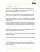
1. MPM‐100GENERALDESCRIPTION ........................................................................................................................ 1
1.1. Normal Operating Mode ......................................................................................................................... 1
1.2. Discharge Mode ...................................................................................................................................... 1
1.3. Resistance Test Mode ............................................................................................................................. 1
1.4. Alarm Features ....................................................................................................................................... 1
1.5. Controlled Run Down Test ..................................................................................................................... 2
1.6. MPM-100 Features ................................................................................................................................. 2
1.7. Battery Monitor Data Manager (BMDM) Program Features ................................................................. 2
1.8. Optional and additional Accessories....................................................................................................... 3
2. PANEL CONTROLS AND INDICATORS ............................................................................................................... 5
2.1. Panel Controls and Indicators ................................................................................................................. 5
3. MPM-100 CONFIGURATIONS .......................................................................................................................... 8
3.1. MPM Model Number Description .......................................................................................................... 8
3.2. MPM Configuration Options .................................................................................................................. 9
4. MPM-100 SPECIFICATIONS ........................................................................................................................... 11
4.1. Fuses On PC Board (Not user replaceable) .......................................................................................... 11
4.2. Measurement Range/Inputs .................................................................................................................. 11
5. COMMUNICATIONOPTIONS ................................................................................................................................ 13
Drawings
IMPORTANTNOTE:
Thedrawingsinthismanualmaynotbethemostrecentrevisionandareincludedforreferenceonly.
RefertotheEngineeringDrawingPackageincludedwithyoursystemforthenewestdrawings.
Drawingsinthismanualmaybeforreferenceonlyorsupersededbylaterdrawings.Forthe
latest
information,refertothedrawingssuppliedwithyoursystem.
GeneralAssembly BDS‐154‐B557
TableofFigures
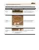
Figure 1. Shunt/Shunt Adapters .............................................................................................................................. 3
Figure 2. Ambient Temperature Probe 2900–029 .................................................................................................. 3
Figure 3. Electrolyte Temperature Probe 2900–010 ............................................................................................... 3
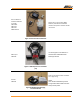
Figure 4. External network interface ...................................................................................................................... 4
Figure 5. 600 amp Current Transducer (CT) ......................................................................................................... 4
Figure 6. Multitel Float Charging Current Probe Kit ............................................................................................. 4
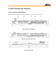
Figure 7. Rear Panel with RJ45 .............................................................................................................................. 5
Figure 8. Rear Panel with RS–232 ......................................................................................................................... 5
Figure 9. Front Panel .............................................................................................................................................. 5
Figure 10. Front Panel Indicators Close up ............................................................................................................ 6
Figure 11. Front Panel Connector and Controls ..................................................................................................... 6
Figure 12. Rear Panel Connectors .......................................................................................................................... 7
Figure 13. MPM 12V Systems Configuration Options Chart ................................................................................. 9
Figure 14. MPM 24V - 36V Systems Configuration Options Chart .................................................................... 10
Figure 15. MPM 38V - 60V Systems Configuration Options Chart .................................................................... 10
Figure 16. MPM 60V - 120V Systems Configuration Options Chart .................................................................. 11
Figure 17. MPM Model Number Communication Option A ............................................................................... 13