MPM‐100 Monitor Product Description Guide 3103 No. Andrews Ave. Ext. Pompano Beach, FL 33064 Tel: (954) 623‐6660 Fax: (954) 623‐6671 www.alber.com 4200‐062 Rev 2.
Copyright and Disclaimer MPM‐100 Product Description Guide Document Revision 2.01 Part Number 4200‐062 Revision History Revision Date of Change Description of Change By 2.00 11/04/2004 Original Document ED 2.01 01/26/2012 Minor edits and reformatting and pagination MS Albér MPM-100 Product Description Guide Part Number 4200–062 ©2012 Albércorp. All rights reserved. Albércorp, 3103 North Andrews Avenue Extension, Pompano Beach FL 33064.
Table of Contents 1. MPM‐100 GENERAL DESCRIPTION ........................................................................................................................ 1 1.1. Normal Operating Mode ......................................................................................................................... 1 1.2. Discharge Mode...................................................................................................................................... 1 1.3.
Figure 18. MPM Model Number Communication Option B................................................................................ 13 Figure 19. MPM Model Number Communication Option C................................................................................ 14 Figure 20. MPM Model Number Communication Option D ............................................................................... 14 Figure 21. MPM Model Number Communication Option E ........................................................
1. MPM‐100 General Description The MPM‐100 is a stand‐alone monitor for communication and power industry applications. What sets Albér monitors apart from others is their ability to provide early warning of battery problems. The monitor checks the state of health of each cell by performing a proactive resistance test, a reliable predictor of battery performance.
1.5. Controlled Run Down Test You can program time intervals (in days) and length of time (in minutes) to have a contact closure optionally put the system on battery. During this time, the system treats the condition as a discharge and saves the changing parameters to a discharge record for playback and analysis. 1.6. MPM-100 Features This section describes standard and optional MPM‐100 features. NOTE: Some features require optional accessories or are unit configuration dependent.
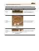
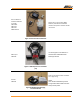
1.8. Optional and additional Accessories The standard optional accessories are shown here, others are also readily available 954‐623‐6660. Optional and Additional Parts Description Photo Shunt 4720–017 Purpose Shunt for measuring discharge current. PHOTOS and PART NUMBERS VARY WITH CONFIGURATION REQUIREMENTS Figure 1. Shunt/Shunt Adapters Ambient temperature probe 2900–029 Temperature probe that hangs free for ambient temperature measurement. Refer to drawing BDS–159–A421.
External Network Interface 2025–063 to include 2025–063P 2025–118 2025–120 4000–047R1.0 Please refer to part number 4000– 047R1.0, UDS‐10 External Network Interface Setup User’s Guide for further instructions. Figure 4. External network interface Use Drawing BDS–1120–A483 Rev C ‐ PHOTOS VARY DEPENDING UPON MODEL(S) CHOSEN 600 amp CT 5610‐016 Figure 5. 600 amp Current Transducer (CT) Float current measurement transducer for a single string.
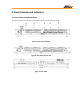
2. Panel Controls and Indicators 2.1. Panel Controls and Indicators This section describes the front and rear panels that comprise a typical MPM–100 system. Figure 7. Rear Panel with RJ45 Figure 8. Rear Panel with RS–232 Figure 9.
SCAN Flashes GREEN (G) during normal operating conditions ALARM When RED (R) – indicates alarm condition detected ALARM DISABLE When RED (R) – indicates user has disabled alarm reporting using BMDM software. RESISTANCE TEST ERROR Shows GREEN (G) as it performs a manual or automatic resistance test. When flashing RED (R) – indicates hardware failure is detected Figure 10.
Local Port May be an RS– 232 or an RJ– 45 network port (LAN). The front panel Local Port Switch enables this port. J2 Provides for alarm (Parameter & System) & digital input relay connections on all MPM configurations. Two sets of dry Form C alarm contacts are also available. Do not use for current transducers if J5 is available. J5 J1, J3, J4, J6, J7 Current Transducer CT connector – optional.
3. MPM-100 Configurations This section is an overview of the MPM‐100 monitor configurations. 3.1. MPM Model Number Description The MPM can accommodate up to 30 different battery configurations, which may be modified for nonstandard battery configurations. (For example, a 1 x 60 configuration can have 59 cells.) The MPM‐100 model numbers are structured as follows. 1001‐nnnA xxxxxx MPM model.
3.2. MPM Configuration Options To determine MPM hardware configuration, cross‐reference the model number using the standard MPM Configuration Options Chart. For special configurations or custom system integration for OEM applications, contact Albér at 954‐623‐6660. Model Configuration Description Number 12V Systems 398 MPM‐100‐1x10x1* 1 string of 10 – 1v cells in series. 399 MPM‐100‐2x10x1 2 strings in parallel of 10 – 1v cells in series.
380 381 374 343 344 345 330 331 332 333 MPM‐100‐3x4x6 MPM‐100‐4x4x6 MPM‐100‐1x3x8 MPM‐100‐2x3x8 MPM‐100‐3x3x8 MPM‐100‐4x3x8 MPM‐100‐1x2x12 MPM‐100‐2x2x12 MPM‐100‐3x2x12 MPM‐100‐4x2x12 *1 volt cells are NiCd 3 strings in parallel of 4 – 6v modules in series. 4 strings in parallel of 4 – 6v modules in series. 1 string of 3 – 8v modules in series. 2 strings in parallel of 3 – 8v modules in series. 3 strings in parallel of 3 – 8v modules in series.
389 387 409 397 357 358 391 359 376 377 390 412 356 MPM‐100‐1x100x1 MPM‐100‐1x54x2 MPM‐100‐1x56x2 MPM‐100‐1x58x2 MPM‐100‐1x60x2 MPM‐100‐1x30x4 MPM‐100‐1x18x6 MPM‐100‐1x20x6 MPM‐100‐1x15x8 MPM‐100‐2x15x8 MPM‐100‐1x8x12 MPM‐100‐2x9x12 MPM‐100‐1x10x12 1 string of 100 – 1v cells in series. 1 string of 54 – 2v cells in series. 1 string of 56 – 2v cells in series. 1 string of 58 – 2v cells in series 1 string of 60 – 2v cells in series. 1 string of 30 – 4v modules in series.
Alarm reset. Normally‐open dry contact required. *Optional temperature and current transducers are required. Actual number of inputs are model dependent. Contact Alber for additional information 954‐623‐ 6660. Outputs Three programmable relay contact configured to N/O or N/C Parameters alarm contact: one Form C alarm relay contact, 2A at 30VDC. Hardware failure or power failure alarm contact: one Form C alarm relay contact, 2A at 30VDC.
Agencies UL listed. File number E212234. CE approved. 5. Communication Options This section describes the letter used in the second position of the MPM model number. Refer to the MPM‐100 Configurations section for more details. Communication Option A MPM Dedicated Phone Line OR RS‐232 Phone Line PC Option A This is for one MPM that will be accessed by one PC, either locally with an RS‐232 connection or via telephone connection.
Communication Option C MPM Dedicated Phone Line RS‐232 Phone Line Phone Line PC 2 PC 1 PC 5 Phone Line Phone Line PC 4 PC 3 Option C This is for one MPM that will be accessed locally by one PC via an RS‐232 connection and That will also be accessed by additional PCs via a telephone connection.
Communication Option E MPM Ethernet Option Card HUB PC 1 PC 3 PC 2 Option E This is for one MPM that will be accessed by two or more PCs locally. This option requires installation of the LAN option in the MPM, and This option also requires connection of the MPM to an existing LAN or installation of a LAN. The LAN can be set up to allow MPM access via the Internet. Figure 21.
Communication Option G MPM 1 MPM 2 Fiber optic Telco Serial Port Multiplexer Dedicated phone line Phone Line Phone Line PC 1 PC 2 Phone Line Phone Line PC 3 PC 4 Option G This is for two to 16 MPMs that will be accessed by one or more PCs via a phone line connection, and There will be one phone line for up to 16 MPMs. A Telco Serial Port Multiplexer is required.
Communication Option J MPM 1 MPM 2 Fiber optic Telco Serial Port Multiplexer Dedicated phone line RS-232 Serial Port Multiplexer RS‐232 PC 5 Phone Line Phone Line Phone Line PC 1 PC 2 Phone Line PC 3 PC 4 Option J This is for two to 16 MPMs that will be accessed by one PC via a serial connection and other PCs via a phone line connection, and There will be one phone line for up to 16 MPMs. An RS‐232 Serial Port Multiplexer is required.
Communication Option L MPM Ethernet Option Card MPM Option L This is for two or more MPMs that will be accessed via a LAN and/or an Internet connection. This option requires installation of the LAN option in the MPMs, and This option also requires connection of each MPM to an existing LAN or installation of a LAN. Ethernet Option Card HUB PC 1 PC 2 PC 3 Figure 27. MPM Model Number Communication Option L 4200-062 18 Revision 2.