
User Guide


Programming Battery Setup for the BDS
18-12
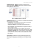
High Cell Voltage Warning (volts) - Type a value between the Low Cell Voltage and High
Cell Voltage levels. This setting affects the bar graph colors on the Cell Voltage String View
screen. During normal float condition, the bar colors change as follows:
High Violation ................... Red
Warning ............................ Blue
Normal .............................. Green
Low Violation .................... Yellow
Out of Range Values ........ Maroon
Negative Cell Voltage ....... Black
String View > Setup|Battery|Float Alarms|Input Level then Save or Cancel
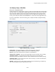
Intertier Resistance Input Level - Click Input Level to display the Input Alarm Level box.
Type the resistance alarm level threshold (in microhms) for each intertier. The cell numbers
in this box are the lower of the two cell numbers across which the intertier is connected.
(These cell numbers are selected under Battery Setup|Parameters.)
Note: The charger cable is only used for BDS and is intended to only be used for individual
thresholds.
Figure 67. Input Alarm Level
(Intertier Resistance Alarm Level)
Percentage for Warning - Determines the violation threshold that causes a Warning battery
status. The value entered is a percentage of the internal resistance alarm. For example, if the
internal resistance alarm is set to 100 microhms and the percentage for warning is 75%, the
system issues a warning when the internal resistance is between 75 and 100 microhms. When
the value exceeds 100 microhms, the system issues an alarm. Warning status is displayed
only on the String Status and Historical Events screens, not on the Alarms screen.
<-----Normal-----75%<-----Warning----->100%-----Alarm----->
Latch - When selected, the alarm contact stays energized until manually reset. If not selected,
the alarm contact de-energizes when the alarm condition clears.
Bar Colors for all
Normal and
Violation Types