
Installation Guide

2
670 Series
compound to the external pipe threads. For anged
bodies, use suitable line gaskets and approved
piping and bolting practices. Install the regulator
in any position desired, unless otherwise specied,
but be sure ow through the body is in the direction
indicated by the arrow on the body.
Note
It is important that the regulator be
installed so that the vent hole in the
spring case is unobstructed at all
times. For outdoor installations, the
regulator should be located away
from vehicular trafc and positioned
so that water, ice, and other foreign
materials cannot enter the spring
case through the vent. Avoid placing
the regulator beneath eaves or
downspouts, and be sure it is above
the probable snow level.
Overpressure Protection
The recommended pressure limitations are
stamped on the regulator nameplate. Some type of
overpressure protection is needed if the actual inlet
pressure exceeds the maximum operating outlet
pressure rating. Overpressure protection should
also be provided if the regulator inlet pressure
is greater than the safe working pressure of the
downstream equipment.
Regulator operation below the maximum pressure
limitations does not preclude the possibility of
damage from external sources or debris in the line.
The regulator should be inspected for damage after
any overpressure condition.
Startup
The regulator is factory set at approximately
the midpoint of the spring range or the pressure
requested, so an initial adjustment may be required
to give the desired results. With proper installation
completed and relief valves properly adjusted, slowly
open the upstream and downstream shutoff valves.
Adjustment
To change the outlet pressure, remove the closing
cap or loosen the locknut and turn the adjusting
screw clockwise to increase outlet pressure or
counterclockwise to decrease pressure. Monitor
the outlet pressure with a test gauge during the
adjustment. Replace the closing cap or tighten the
locknut to maintain the desired setting.
Taking Out of Service (Shutdown)
!
WARNING
To avoid personal injury resulting from
sudden release of pressure, isolate
the regulator from all pressure before
attempting disassembly.
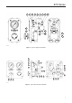
Parts List
Key Description
1 Regulator
2 Gauge
3 Panel
4 Clamp Bar
5 Hex Nut
6 Machine Screw
7 Tubing
8 Fitting
9 Fitting
10 Nipple
11 Fitting
12 Tubing
13 Changeover Valve
15 Gauge Service Marking
16 Machine Screw
17 Fitting
18 Valve Dial
19 Machine Screw
20 Tubing
24 Bleed Orice and Screen Assembly
25 Serial Plate
26 Hex Nut
27 Fitting
28 Fitting