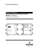
Emerson Energy Systems UM5C05C ( 169-2081-501 ) Helios Modular Switch Mode Rectifier 200I/48NT5C05C Installation and User Manual HELIOS V OL T V O LT CA L AM P CUR CA L CL AD J I EQ L AD J TH S D 0 HV SD RF A SEN F A IL FA N A LM EQ L V O L T+ V O U T- E QL A C ON FF 1 1 .0 A F F2 1 .0A F LT CL F LT A DJ A C/C A H VS D A DJ I S T UP DL Y S LS I D C /C C P0745680 Standard 6.
Helios Modular Switch Mode Rectifier 200I/48 NT5C05C Installation and User Manual Manual Number : UM5C05C ( 169-2081-501 ) Manual Status : Standard Manual Issue : 6.00 Release Date : October 2001 P0745680 Copyright 2001 Astec International Ltd All Rights Reserved Published in Canada The information contained in this manual is the property of Astec International Ltd and is subject to change without notice.
Publication history October 2001 Standard Issue 6.00. Manual restructured and updated to reflect Emerson Energy Systems and Emerson Network Power identities. ( ECN 102-26804 ) March 1998 Issue 5.0. Standard. Reference change from NT5C05CB to NT5C05C. July 1997 Issue 4.0. Standard EMI compliance information and table of content numbering corrections. June 1995 Issue 3.0. Standard. Revised rectifier installation procedure in a cabinet. September 1994 Issue 2.0. Standard.
Publication history This page is left blank intentionally. UM5C05C P0745680 Standard 6.
Contents 1. General information .................................................................................... 11 1.1. Purpose of this manual .............................................................................. 11 1.2. Models and mounting configurations ......................................................... 12 2. Specifications .............................................................................................. 13 2.1. Mechanical and electrical specifications ................
Contents 6. Maintenance................................................................................................. 49 6.1. Replacing the air filter ................................................................................ 49 6.2. Replacing the fan unit ................................................................................ 49 6.3. Calibrating the Volt / Amp Multimeter......................................................... 50 6.4.
Contents 9 Procedure 6 - Connecting the ac male plug between the NT5C05CC rectifier and the ac female plug in a 1200 A cabinet .................................. 27 Procedure 7 - Connecting the NT5C05CC to the controller................................. 28 Procedure 8 - Connecting an NT5C05CC rectifier directly to a controller ........... 29 Procedure 9 - Starting up the rectifier .................................................................. 46 Procedure 10 - Replacing the fan unit ....................
Contents This page is left blank intentionally. UM5C05C P0745680 Standard 6.
1. General information 1.1. Purpose of this manual This manual provides installation, operation and maintenance information for the NT5C05CA / CB / CC 200I modular switch mode rectifiers with an input voltage of 380 / 415 V ac and an output capacity of 200 A at a nominal voltage of –48 volts. This manual covers all applications of the rectifier referred to as the 200I ( “I” standing for “International” ) market.
General information 1.2. Models and mounting configurations Two models of 200I rectifiers are available : • Models NT5C05CA / CB, without an ac cable • Model NT5C05CC, equipped with an ac cable terminated with a male plug Up to six switch mode 200I rectifiers can be installed in a 23-inch NT6C43CB 1200 A cabinet or in an NT6C40 type frame. The cabinet is specifically designed to provide modularity within a very compact unit.
2. Specifications 2.1. Mechanical and electrical specifications Table 1 - Mechanical specifications of the rectifier 10.0 inches ( 25.4 cm ) Height : Depth : 22.0 inches ( 55.9 cm ) Width : 20.5 inches ( 52.1 cm ) Weight : 92.
Specifications 2.2. Operation specifications and ambient conditions Table 3 - Operation specifications of the rectifier Output regulation : At the output terminals, the voltage is within ±0.5% of the set voltage value for all specified input and output variations, and within ±1% for any combination of specified input, output and ambient conditions. Temperature drift : Unless otherwise stated, all input and output parameters such as input voltage range, output current and voltage, current limit, etc.
Specifications 15 Table 4 - Ambient conditions for the rectifier Operating conditions A minimum airflow clearance of 2 inches ( 5 cm ) is required at the rear of the rectifier. The rectifier will operate properly under the following conditions. Temperature: 32°F to 122°F ( 0°C to +50°C ) 32°F to 104°F ( 0°C to +40°C ) with air filters Humidity: Transportation conditions 0 to 95% RH ( non-condensing ) at 4 kPa max. equiv. to 7,000 ft.
Specifications 2.3. Mechanical and electrical specifications of a 1200 A cabinet Table 5 - Mechanical specifications of the NT6C43CB 1200 A cabinet 84.00 inches ( 213.36 cm ) Height : Depth : 23.63 inches ( 60.0 cm ) Width : 23.63 inches ( 60.0 cm ) Table 6 - Electrical specifications of the NT6C43CB 1200 A cabinet 2.4.
3. Installation 3.1. Mounting configurations The NT5C05CA / CB / CC rectifiers are designed for installation in a 1200 A cabinet ( NT6C43CB ) or in a standard frame ( NT6C40 or equivalent ). In this chapter, a different procedure is provided for each mounting method. The rectifiers are shipped loose, not mounted in the frame or cabinet. Upon reception, remove the rectifier from its shipping carton and inspect it for physical damage. Report any damage to your immediate supervisor. 3.2.
Installation CAUTION Preventing damage caused by over-tightening Do not over-tighten nuts and bolts. Over-tightening can strip the threads or break the bolts. Apply the appropriate torque values. CAUTION Personal safety and protecting the equipment Use a dolly truck, forklift, or hoist whenever possible when handling and moving the equipment, as power equipment is heavy. If a forklift is used, do not remove the packing material before having moved the equipment to its final location.
Installation 19 WARNING Generator requirements for Emerson Energy Systems Power Systems For information on selecting ac generators that will effectively maintain peak performance and operating characteristics, for all Astec APS power systems, go to the partners’ section of the Emerson Energy Systems web site at www.EmersonEnergy-NA.com.
Installation DANGER Short circuit hazard The rectifiers, and the batteries in particular, can deliver high current if a short to ground occurs. When working on live equipment, remove all personal jewellery, use properly insulated tools, and cover any live busbars with a insulating sheet of canvas to prevent short circuits that could be caused by falling tools or parts. 3.3.1.
Installation 21 in the concrete floor, the secondary anchor locations may be used. An optional cabinet isolation kit is available consisting of four anchor bushings and a base pad. If this kit is installed, place the pad on the floor and the bushings on the anchors, and position the cabinet on top. Figure 3 - Anchoring the cabinet 590 mm (23.13 po.) 520 mm (20.42 po.) 600 mm (23.56 po.) SECONDARY LOCATION FOR FLOOR ANCHORS + PRIMARY LOCATION FOR FLOOR ANCHORS + 526 mm (20.68 po.
Installation Procedure 2 - Installing a rectifier in a cabinet ( continued ) Step Action 4 Place the rectifier on the L-shaped guides located in the lowest position of the cabinet and slide it towards the rear until the mounting brackets come into contact with the frame of the cabinet. The front of the rectifier should be flush with the front of the cabinet and the output bussing should be in contact with the riser busbars located at the rear of the cabinet.
Installation 23 3.5. Connecting the dc output terminals to the busbars The dc outputs of the rectifier are connected to the busbars as illustrated in Figure 5.
Installation 3.5.1. Securing the dc output terminals to the busbars in a 1200 A cabinet For cabinet applications, no dc cabling is required; the output terminals of the rectifier are connected directly to the busbars. Procedure 3 - Securing the dc output terminals to the busbars of the cabinet Step Action 1 Connect the BAT GRD output terminal of the rectifier to the BR busbar, and the –48 V output terminal of the rectifier to the –48 V busbar located at the rear of the cabinet.
Installation 25 DANGER Hazardous potentials Input voltage to the cabinet is at a hazardous potential. Make sure the power is OFF and that the lever in the ac service panel is locked in the OFF position before attempting to connect the input line voltage to the ac box of the cabinet. Procedure 5 - Cabling the ac input to the NT5C05CA / CB rectifiers Step Action 1 Install the ac breaker ( 30 A / 3 phase per rectifier ) in the 380 / 415 volts ac service panel and lock it in the open ( OFF ) position.
Installation Figure 6 - Cabling ac the NT5C05CA / CB rectifiers SIGNAL CABLES TO THE PLANT CONTROLLER AC FEED TO RECTIFIERS PART OF OPTIONAL KIT P0872151 A CABLE TIE A SIGNAL CABLE Note: Dress the cables carefully to clear the insertion path of the rectifier.
Installation 27 Procedure 6 - Connecting the ac male plug between the NT5C05CC rectifier and the ac female plug in a 1200 A cabinet Step Action 1 Install the ac breaker ( 30 A / 3 phases per rectifier ) in the 380 / 415 volts ac service panel. 2 Put the ac breaker for the NT5C05CC rectifier, located in the ac service panel, to OFF. 3 Run the metric no. 25 ( 10 AWG ) ac supply cable ( 3 conductors and ground ) to the female receptacle ( see Figure 8 ).
Installation 3.7. Connecting the control signals For all applications with conventional controllers ( such as NT6C25BA or NT6C25BB ) or front access controllers ( NT6C25FA ), execute the steps contained in Procedure 7 to connect the NT5C05CC rectifier ( see Figure 9 ). Procedure 7 - Connecting the NT5C05CC to the controller Step Action 1 Connect each rectifier to the NT6C43PB board ( positions J1 to J6 ), located at the top front of the cabinet or frame, with P0747000 cables.
Installation 29 Procedure 8 - Connecting an NT5C05CC rectifier directly to a controller Step 1 Action If an NT6C43PB interconnect board is not available, each rectifier must be connected directly to the controller with the following cables : • P0723784, P0723785 or P0723786 ( for conventional controllers ) • P0723708, P0723709 or P0723210 ( for front access controllers ) end For controllers not manufactured by Emerson Energy Systems see Table 12 in the " Functional Description " chapter describing
Installation Table 9 - Pin assignment for connector J13 Pin Function J13-1 SH+ ( rectifier 1 ) J13-2 SH− ( rectifier 1 ) J13-3 SH+ ( rectifier 2 ) J13-4 SH− ( rectifier 2 ) J13-5 SH+ ( rectifier 3 ) J13-6 SH− ( rectifier 3 ) J13-7 SH+ ( rectifier 4 ) J13-8 SH− ( rectifier 4 ) J13-9 SH+ ( rectifier 5 ) J13-10 SH− ( rectifier 5 ) J13-11 SH+ ( rectifier 6 ) J13-12 SH− ( rectifier 6 ) UM5C05C P0745680 Standard 6.
4. Functional description 4.1. Overview 4.1.1.
Functional description 4.1.3. Monitoring and control circuits The monitoring and control circuits offer the following characteristics : • soft start • rectifier fail alarm ( RFA ) • control for local and remote equalize ( EQL ) • temporary release ( TR ) • thermal shutdown ( THSD ) • input ac monitoring • local and remote high voltage dc shutdown ( HVSD ) • local and remote HVSD reset • fan failure detection 4.1.4.
Functional description 33 4.2.2. Switches, controls and LEDs There are switches and potentiometers on the front panel to adjust the operating parameters of the rectifier. The LED indicators indicate the operating and alarm conditions. Figure 10 - Front panel controls and LEDs VOLT VOLT CAL AMP CUR CAL CL ADJ EQL ADJ VOLT/AMP THSD RFA HVSD FAN ALM VOUT+ SEN FAIL EQL EQL AC ON CL FF1 1.0A FF2 1.
Functional description 4.2.3.
Functional description 35 HVSD ( high voltage shutdown ) The rectifier monitors itself for high voltage and will shut down when its output voltage exceeds a preset adjustable value ( between -52 V and -60 V ). RFA ( rectifier failure alarm ) The rectifier monitors its operation and triggers a global RFA if it detects an internal failure, causing the RFA LED to light up.
Functional description Table 11 - Adjusting the potentiometers and switches Potentiometers CL ADJ Description Current limit adjust ( 100 A to 210 A ) CUR CAL Current reading calibration EQL ADJ Equalize voltage adjust ( 0 V to −4 V ) FLT ADJ Float voltage adjust ( −46 V to −58 V ) HVSD ADJ High voltage shutdown adjust ( −52 V to −60 V ) VOLT CAL Voltage reading calibration Switches EQL / FLT SLS / FS ST UP DELAY VOLT / AMP Description Equalize / Float selection switch Slope load sharing / F
Functional description 37 VOLT / AMP digital meter switch This switch is used to select the measurement display mode of the digital meter. The output voltage or the output current modes can be selected. VOUT+, VOUT− − test points These test points are used to measure the voltage at the point of regulation. A 5 kohm resistor is placed in series with both sensing leads to prevent short-circuits at the jack terminals. The resistor may affect reading accuracy, depending on the impedance of the meter.
Functional description The rectifier can be started when it is connected across a completely discharged battery without requiring human intervention or operating protective devices. A transition from constant voltage operation to constant current operation and from constant current operation to constant voltage operation occurs automatically, as determined by the output current. The current limiting circuit is functional in float and equalize modes. 4.2.8.
Functional description 39 Example 1 : If the rectifier is expected to provide 100 A at 48 V V ( preset ) = 48 V + 0.8 V + ( 100 x 300 mV ) 200 V ( preset ) = 48 V + 0.8 V + 0.15 V = 48.95 V Example 2 : If the rectifier is expected to provide 40 A at 48 V V ( preset ) = 48 V + 0.8 V + ( 40 x 300 mV ) 200 V ( preset ) = 48 V + 0.8 V + 0.06 V = 48.
Functional description 4.2.9. HVSD ( high voltage shutdown ) HVSD ADJ ( high voltage shutdown adjust ) potentiometer Use this potentiometer to set the internal threshold level at which the local high voltage shutdown condition should occur. Remote HVSD In addition to the local high voltage shutdown feature, the controller of the power plant controller can shut down any rectifier by sending a high voltage shutdown signal, ground ( BAT RTN ) pulse.
Functional description 41 Table 13 - Setting the start-up delay SWITCH # 1 0 6 5 4 3 POSITION 1 1 NOTE: Switches 3 to 6 ( top four switches ) are used to set the start-up delay.
Functional description Remote ON / OFF control TR When a ground signal is applied to the 'Temporary Release' ( TR ) input, the rectifier inhibits its operation and triggers the RFA. When the remote ground signal is discontinued the rectifier returns to normal operation ( see Table 14 ). Start up delay DIP switch The rectifier can provide a start-up delay of from 4 seconds up to 120 seconds, with a resolution of 8 seconds and an accuracy of +1 second.
Functional description 43 Table 14 - Control signal connections on P1 ( continued ) Connection Signal P1-11 NC No connection P1-12 NC No connection P1-13 CB OFF ( NC ) P1-14 RG+ P1-15 TR P1-16 HVSD P1-17 CURRENT SHARE P1-18 RFA ( C ) P1-19 SH+ P1-20 FAN ( NO ) P1-21 GRD P1-22 SENSE FAIL ( NC ) P1-23 NC No connection P1-24 NC No connection P1-25 CB OPEN ( C ) Emerson Energy Systems Description Output breaker OFF ( NC ) Remote sense ( + ) Rectifier temporary released by
Functional description This page is left blank intentionally. UM5C05C P0745680 Standard 6.
5. Operation 5.1. Standard settings The parameters of the NT5C05CA / CB / CC rectifiers are set as indicated in Table 15. For different settings refer to User Manual Voltage_level entitled Voltage Level Limits for Power Plants, Rectifiers and Controllers. Table 15 - Standard settings for the rectifier Parameter Setting Rectifier float output voltage ( FLOAT ) 52.1 ±0.1 V dc Rectifier equalize output voltage ( EQUALIZE ) 52.8 ±0.1 V dc Rectifier high voltage shutdown threshold 56.5 ±0.
Operation 5.2. Starting up and adjusting Procedure 9 - Starting up the rectifier Step Action 1 Put the dc circuit breaker to OFF ( 0 position ). Open the sensing leads by removing the corresponding RC fuse ( when the rectifier is used with a controller ) or by disconnecting the alarm and control cable ( when the rectifier is used without a controller ). 2 Put the ac circuit breaker in the main ac service panel to ON. 3 Put the 25 A, 3Ø, ac circuit breaker of the rectifier being tested to ON.
Operation 47 Procedure 9 - Starting up the rectifier ( continued ) Step Action Adjusting the float voltage 14 Ensure that the EQL / FLT switch is on the FLT position. 15 To adjust the float voltage to the proper level, turn the FLT potentiometer clockwise to increase the voltage or counterclockwise to decrease it. Adjusting the equalize voltage ( EQL ) 16 Set the EQL / FLT switch to EQL. Turn the EQL potentiometer clockwise to increase the voltage or counterclockwise to decrease it.
Operation Procedure 9 - Starting up the rectifier ( continued ) Step 23 Action Turn ON the other rectifiers in the system. Setting the start-up delay 24 Use this feature to reduce the inrush currents when two or more rectifiers are connected to a common ac input. Set the DIP switches on the front panel for the required start-up delay, from 4 to 124 seconds ( see Table 13 ).
6. Maintenance 6.1. Replacing the air filter In dusty environments, the use of air filters is strongly recommended. If used they should be replaced at least once a year. 6.2. Replacing the fan unit The fan unit, consisting of four fans and a fan plate, can be replaced. To install a new fan unit, execute the steps outlined in Procedure 10 and illustrated in Figure 11.
Maintenance CAUTION Preventing short circuits The replacement operation is safe, as only SELV circuitry is present behind the fan assembly. However, due to the possible presence of residual charges in the output circuit, do not use metal tools within the rectifier enclosure. To remove the fan assembly mounting screws you need a screwdriver, but all the other operations described below can and should be performed without any tools.
Maintenance 51 Procedure 11 - Calibrating the meter Step Action 1 Make sure the remote sense leads are disconnected by removing the corresponding RC− fuse from the controller. 2 Set the VOLT/AMP switch to AMP. Set the output load of the plant so the rectifier delivers a current of approximately 100 A. Measure the voltage between VOUT+ and VOUT −, located on the front panel, with a digital meter. 3 Convert this measured voltage to a current value ( 50 mV corresponding to 250 A ).
Maintenance This page is left blank intentionally. UM5C05C P0745680 Standard 6.
7. Troubleshooting Table 16 - Diagnosing system faults Fault symptom The RFA LED is lit. The HVSD LED is lit. Possible causes • No ac input or input is out of bounds ( ac ON LED is extinguished ). • AC Input / dc output circuit breaker is open. • The rectifier has received an HVSD signal from the controller, or a TR signal is present. • An internal high voltage shutdown ( HVSD ) has occurred. • Two cooling fans or fuses have failed. • The inrush fuse has blown.
Troubleshooting Table 16 – Diagnosing system faults Fault symptom The AC ON LED is not lit. The FAN ALM LED is lit. Possible causes • No ac input voltage. • The input circuit breaker is open. • AC voltage is present but is out of operational limits. The unit will restart when the ac returns to the operating level. • AC has just been applied and the rectifier will momentarily start ( after an inrush control delay ). • The fuse of one or both fans has blown. • One or both fans have failed.
8.
Appendix A: Recommended Replacement Parts This page is left blank intentionally. UM5C05C P0745680 Standard 6.
9. Appendix B : Technical service assistance For technical assistance, 24 hours a day / 7 days a week, dial one of the following toll-free numbers. This service complements the services offered by field support organizations such as, the Emergency Technical Assistance Service ( ETAS ), and the Installation Technical Assistance Service ( ITAS ). 9.1. Local toll-free prefixes The following prefixes give access to toll-free numbers in various countries.
Appendix B : Technical service assistance 9.2.
10.
Abbreviations and acronyms RFA Rectifier fail alarm RG+ Remote ground bus ( positive ) RMT ACK Remote acknowledge SEN FAIL Sense fail THSD Thermal shutdown TR Temporary release VCAL Voltage reading calibration UM5C05C P0745680 Standard 6.
Helios Modular Switch Mode Rectifier 200I/48 NT5C05C Installation and User Manual Emerson Energy Systems 2280 Alfred-Nobel Blvd St-Laurent ( Quebec ) Canada H4S 2A4 Manual Number : UM5C05C ( 169-2081-501 ) Manual Status : Standard Manual Issue : 6.00 Release Date : October 2001 P0745680 Copyright 2001 Astec International Ltd All Rights Reserved Published in Canada The information contained in this manual is the property of Astec International Ltd and is subject to change without notice.