389VP Instruction Manual PN 51-389VP/rev.
This page left blank intentionally
Essential Instructions Read this page before proceeding Emerson designs, manufactures, and tests its Rosemount Analytical products to meet many national and international standards. Because these instruments are sophisticated technical products, you must properly install, use, and maintain them to ensure they continue to operate within their normal specifications.
About this document This manual contains instructions for installation and operation of the Model 1066 Smart Transmitter. The following list provides notes concerning all revisions of this document. Rev. Level A II Date 2/01 Notes This is the initial release of the product manual. The manual has been reformatted to reflect the Emerson documentation style and updated to reflect any changes in the product offering. B 7/02 Added 1055 wiring diagrams.
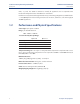
389VP Instruction Manual Table of Contents PN 51-389VP January 2013 Contents Section 1: Description and Specifications 1.1 Features and Applications ............................................................................................1 1.2 Performance and Physical Specification .......................................................................2 1.3 Ordering Information ...................................................................................................
Table of Contents 389VP Instruction Manual January 2013 PN 51-389VP List of Tables No. Title 3-1 ORP of Saturated Quinhydrone Solution (In Millivolts)............................................................13 4-1 Ro and R1 Values for Temperature Compensation Elements ..................................................14 4-2 Temperature vs Resistance of Auto T.C. Elements...................................................................14 5-1 Troubleshooting..................................
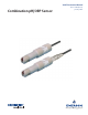
389VP Instruction Manual Section 1: Description and specifications PN 51-389VP January 2013 Section 1: Description and Specifications 1.1 Features and Applications 389VP triple-junction sensors are now offered with SMART capabilities. SMART option becomes enabled when use with the 1056, 1057, 1066, 56 instruments and on 6081P wireless transmitter.
Section 1: Description and specifications 389VP Instruction Manual January 2013 PN 51-389VP tanks, or ponds. The 389VP is suitable for virtually all applications and is compatible with Rosemount Analytical and other manufacturers’ instruments. Installation is easily achieved through the wide variety of mounting configurations. 389VP features a 1 inch (MNPT) front and rear facing connections for insertion, submersion, or flow-through pH and ORP applications. 1.
389VP Instruction Manual PN 51-389VP 1.3 Section 1: Description and specifications January 2013 Ordering Information The 389VP pH/ORP Sensor is offered with a Variopol (VP) connector and uses a mating VP cable (purchased separately). A remote preamplifier (j-box or instrument) must be used with this sensor, unless (-70) preamplifier option is selected. Model 389VP is SMART enable using option (-70). A Variopol cable is required for all first-time installations. See below for cable selection.
Section 1: Description and specifications 389VP Instruction Manual January 2013 PN 51-389VP This page left blank intentionally 4 Description and Specifications
389VP Instruction Manual Section 2: Installation PN 51-389VP January 2013 Section 2: Installation 2.1 Unpacking and inspection Inspect the outside of the carton for any damage. If damage is detected, contact the carrier immediately. Inspect the hardware. Make sure all the items in the packing list are present and in good condition. Notify the factory if any part is missing. If the instrument appears to be in satisfactory condition, proceed to Section 2.2, Mounting.
Section 2: Installation January 2013 2.2.1 389VP Instruction Manual PN 51-389VP Submersion Mounting The 389 and 389VP Sensor has a 1 in. MNPT process connection at the back of the sensor. Utilizing a standard 1 in. union, the sensor may be mounted to a 1 in. SCH 80 CPVC or PVDF standpipe. Tapered pipe threads in plastic tend to loosen after installation.
389VP Instruction Manual PN 51-389VP Section 2: Installation January 2013 FIGURE 2-1.
Section 2: Installation 389VP Instruction Manual January 2013 PN 51-389VP FIGURE 2-2. Submersion Installations DWG. NO. REV. 400389VP12 A WHEN INCH AND METRIC DIMS ARE GIVEN MILLIMETER INCH DWG. NO. 400389VP11 8 REV.
389VP Instruction Manual Section 2: Installation PN 51-389VP January 2013 FIGURE 2-3. Flow Through and Insertion Installations 1-1/2” x 1” Reducing Bushing 1-1/2” x 1” Reducing Bushing STRaigHT flOw SHOwN 1-1/2” Pipe Tee 1-1/2” Pipe Tee aNglE flOw SHOwN flOw 1-1/2” x 1” Reducing Bushing PiPE “y” iNSTallaTiON SHOwN 1-1/2” Pipe “Y” NOTES: Valves and fittings by others. Mount the sensor at least 10° from horizontal. FIGURE 2-4. VP8 Cable, sensor end FIGURE 2-5.
Section 2: Installation 389VP Instruction Manual January 2013 FIGURE 2-6. VP6 81 Wiring PN 51-389VP FIGURE 2-7. VP6 1181 Wiring FIGURE 2-8. VP6 54 Wiring through Remote Junction Box FIGURE 2-9. VP6 54 Wiring 10 FIGURE 2-10.
389VP Instruction Manual PN 51-389VP FIGURE 2-11. VP6 1181, 1050/1060, and 1003/1023 Wiring through Remote Junction Box FIGURE 2-13. VP6 1055-22-32 Wiring Installation Section 2: Installation January 2013 FIGURE 2-12. VP6 2081 Wiring through Remote Junction Box FIGURE 2-14.
Section 2: Installation January 2013 389VP Instruction Manual PN 51-389VP FIGURE 2-15. VP6 81 Wiring through Remote Junction Box FIGURE 2-16. VP6 3081 & 4081 Wiring through Remote Junction Box FIGURE 2-17. VP6 1054 Wiring FIGURE 2-18.
389VP Instruction Manual Section 2: Installation PN 51-389VP FIGURE 2-19. CAS Installation, label information January 2013 FIGURE 2-20. 1054A/B & 2054 VP6 Wiring through a Remote Junction Box FIGURE 2-21.
Section 2: Installation 389VP Instruction Manual January 2013 FIGURE 2-22. SCL-(P/Q) Wiring PN 51-389VP FIGURE 2-23. 2700 Wiring FIGURE 2-23. 54e pH/ORP Wiring. This is the standard VP8 cable wiring.
389VP Instruction Manual PN 51-389VP Section 2: Installation January 2013 FIGURE 2-25. Xmt VP8 Wiring. This is the standard VP8 cable wiring. VP8 cable assembly works both with VP6 and VP8 sensor connector FIGURE 2-26. 1056 VP8 Wiring. This is the standard VP8 cable wiring.
Section 2: Installation January 2013 389VP Instruction Manual PN 51-389VP FIGURE 2-27. 5081 VP8 Wiring. This is the standard VP8 cable wiring.
389VP Instruction Manual Section 3: Start-up and Calibration PN 51-389VP January 2013 Section 3: Start-up and Calibration 3.1 Sensor Preparation Shake down the sensor to remove any air bubbles that may be present at the tip of the pH glass bulb. In most cases, the pH sensor can simply be installed as shipped and readings with an accuracy of ± 0.2 pH may be obtained.
Section 3: Start-up and Calibration 389VP Instruction Manual January 2013 PN 51-389VP 2. Measure and record the pH of the process solution sample with a another temperature compensated, calibrated pH instrument. For best results, standardization should be performed at the process temperature. 3. Adjust the analyzer/transmitter value to the standardized value. 3.3 389VP ORP Most industrial applications have a number of ORP reactions occurring in sequence or simultaneously.
389VP Instruction Manual Section 4: Maintenance PN 51-389VP January 2013 Section 4: Maintenance The 389VP Sensor requires minimum maintenance. The sensor should be kept clean and free of debris and sediment at all times. The frequency of cleaning by wiping or brushing with a soft cloth or brush is determined by the nature of the solution being measured. The sensor should be removed from the process periodically and checked in buffer solutions.
Section 4: Maintenance 389VP Instruction Manual January 2013 PN 51-389VP TABLE 4-1. RO and R1 values for temperature compensation elements Temperature RO R1 Compensation Element 3K 2934 .0045 PT-100 107.7 .00385 TABLE 4-2. Temperature vs. Resistance of auto T.C. elements Resistance Temperature °C (Ohms) ±1% 0 10 20 25 30 40 50 60 70 80 90 100 3K PT-100 2670 2802 2934 3000 3066 3198 3330 3462 3594 3726 3858 3990 100.0 103.8 107.7 109.6 111.5 115.4 119.2 123.1 126.9 130.8 134.6 138.5 4.
389VP Instruction Manual PN 51-389VP Section 4: Maintenance January 2013 476 +20 mV at 25°C when used with a saturated KCl/AgCl reference electrode and platinum measuring electrode. Some tolerance in mV values is to be expected due to the rather large liquid reference junction potentials that can arise when measuring this strongly acidic and concentrated solution.
Section 4: Maintenance 389VP Instruction Manual January 2013 PN 51-389VP This page left blank intentionally 22 Maintenance
389VP Instruction Manual Section 5: Troubleshooting PN 51-389VP January 2013 Section 5: Troubleshooting TABLE 5-1. Troubleshooting Trouble P robable C aus e R emedy Meter reads off scale (Display reads overrange). Defective preamplifier. Replace preamplifier (for code 02 sensors). For code 01, replace sensor. T.C. element shorted. Check T.C. element as instructed in Section 4.2 and replace sensor if defective. Sensor not in process or sample stream is low.
Section 5: Troubleshooting 389VP Instruction Manual January 2013 PN 51-389VP accESSORiES 24 PART 24281-00 24281-01 24281-02 24281-03 24281-04 24281-05 24281-06 24281-07 24281-08 DESCRIPTION 15 ft. VP8 cable 25 ft. VP8 cable 2.5 ft. VP8 cable 50 ft. VP8 cable 100 ft. VP8 cable 4 ft. VP8 cable 10 ft. VP8 cable 20 ft. VP8 cable 30 ft. VP8 cable 23645-06 23645-07 15 ft. cable with mating VP6 connector, prepped with BNC on instrument end 15 ft.
389VP Instruction Manual Section 6: Return of Material PN 51-389VP January 2013 Section 6: Return of Material 6.1 General To expedite the repair and return of instruments, proper communication between the customer and the factory is important. A return material authorization number is required. Call 1-800-6547768 or (949) 757-8500. The “Return of Materials Request” form is provided for you to copy and use in case the situation arises.
Section 6: Return of Material 389VP Instruction Manual January 2013 PN 51-389VP •IMPORTANT! This form must be completed to ensure expedient factory service.
389VP Instruction Manual Warranty PN 51-389VP January 2013 WARRANTY Seller warrants that the firmware will execute the programming instructions provided by Seller, and that the Goods manufactured or Services provided by Seller will be free from defects in materials or workmanship under normal use and care until the expiration of the applicable warranty period.
389VP Instruction Manual January 2013 PN 51-389VP facebook.com/EmersonRosemountAnalytical 8 AnalyticExpert.com Credit Cards for U.S. Purchases Only. twitter.com/RAIhome youtube.com/user/RosemountAnalytical Emerson Process Management ©2013 Rosemount Analytical, Inc. All rights reserved. 2400 Barranca Parkway Irvine, CA 92606 USA Tel: (949) 757-8500 Fax: (949) 474-7250 The Emerson logo is a trademark and service mark of Emerson Electric Co.