Installation Manual P/N 20002172, Rev.
©2008, Micro Motion, Inc. All rights reserved. ELITE and ProLink are registered trademarks, and MVD and MVD Direct Connect are trademarks of Micro Motion, Inc., Boulder, Colorado. Micro Motion is a registered trade name of Micro Motion, Inc., Boulder, Colorado. The Micro Motion and Emerson logos are trademarks and service marks of Emerson Electric Co. All other trademarks are property of their respective owners.
Before You Begin Before You Begin This manual describes how to install a Micro Motion® T-Series sensor. The following information is provided in this manual: Customer service . . . . . . . . . . . . . . . . . . . . . . . . . . . . . . . . . . . . . . . . . . . . . . . page 1 Definitions . . . . . . . . . . . . . . . . . . . . . . . . . . . . . . . . . . . . . . . . . . . . . . . . . . . . . page 2 European installations . . . . . . . . . . . . . . . . . . . . . . . . . . . . . . . . . . . . . . . . . . .
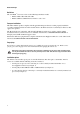
Before You Begin Definitions The term MVD™ transmitter refers to the following transmitter models: • Models 1500, 1700, 2500, and 2700 • Models 3500 and 3700 with sensor interface code 5 or 6 European installations This Micro Motion product complies with all applicable European directives when properly installed in accordance with the instructions in this manual. Refer to the EC declaration of conformity for directives that apply to this product.
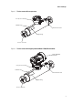
Before You Begin Figure 1 T-Series sensor with core processor Core processor housing Calibration tag Flow direction arrow Approval tag Process connection Figure 2 T-Series sensor with integrally mounted Model 1700/2700 transmitter Model 1700/2700 transmitter Core processor housing Calibration tag Flow direction arrow Approval tag Process connection 3
Determining a Location Figure 3 T-Series sensor with junction box Junction box Calibration tag Flow direction arrow Approval tag Process connection Step 1 Determining a Location Choose a location for the sensor based on the requirements described in this section. The following general guidelines can help you select an appropriate location for the sensor. Full flow tubes For optimal performance, the sensor tubes should remain full of process fluid.
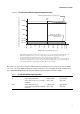
Determining a Location T-Series sensor ambient and process temperature limits Mount transmitter remotely; use junction box 125.
Determining a Location Maximum wiring distances If the transmitter is mounted remotely from the sensor, the maximum distance between the sensor and transmitter depends on cable type. See Table 2.
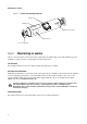
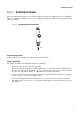
Orienting the Sensor Step 2 Orienting the Sensor The sensor will function properly in any orientation if the sensor tubes remain filled with process fluid. Micro Motion recommends orienting the sensor in a vertical pipeline, with process fluid flowing upward through the sensor (see Figure 5). Figure 5 Recommended sensor orientation Flow Self-draining applications T-Series sensors can be installed to be self-draining in any orientation.
Orienting the Sensor Figure 6 Eccentric reducer Eccentric reducer Sensor housing Process end connection is the same size as the sensor connection. Note: As part of the cleaning process, skid-based systems may be purged with nitrogen at the end of the cleaning cycle. When using eccentric reducers, it is possible to trap gas in the section of process piping adjacent to the reducer. Sensor performance can be impacted by intermittent flow of the captured gas in a liquid fluid stream.
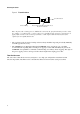
Mounting the Sensor Step 3 Mounting the Sensor Use your common practices to minimize torque and bending load on process connections. To reduce the risk of condensation or excessive moisture, the conduit opening should not point upward (if possible). The conduit opening of the junction box or core processor can be rotated freely to facilitate wiring. Figure 7 illustrates how to mount the sensor. Do not use the meter to support the piping.
Wiring Step 4 Wiring Hazardous area installations If you are installing the sensor in a hazardous location, verify that the hazardous classification information printed on the sensor tag matches the environment in which the sensor will be installed. Failure to comply with the requirements for intrinsic safety in a hazardous area could result in an explosion. Make sure the hazardous area specified on the sensor approval tag is suitable for the environment in which the sensor will be installed.
Wiring Figure 8 Micro Motion cable gland and heat shrink 4 1/2 in (114 mm) 3/4 in (19 mm) Gland nut Gland clamping insert 7/8 in (22 mm) 7/8 in (22 mm) Gland body Shielded heat shrink 4. For connection at the core processor housing, prepare shielded cable as follows (for armored cable, omit steps d, e, f, and g): a. Strip 4 1/2 inches (114 mm) of cable jacket. b. Remove the clear wrap that is inside the cable jacket, and remove the filler material between the wires. c.
Wiring Figure 10 Applying the heat shrink g. Position gland clamping insert so the interior end is flush with the heat shrink. h. Fold the cloth shield or braid and drain wires over the clamping insert and approximately 1/8 inch (3 mm) past the O-ring. Figure 11 Folding the cloth shield i. Install the gland body into the core processor housing conduit opening. Figure 12 Gland body and core processor housing 5. Insert the wires through the gland body and assemble the gland by tightening the gland nut.
Wiring Figure 13 Connecting the wires at the core processor Terminal 1 Power supply + (Red wire) Terminal 4 RS-485B (Green wire) Terminal 3 RS-485A (White wire) Terminal 2 Power supply – (Black wire) Core processor housing internal ground screw • For connections to earth ground (if core processor cannot be grounded via sensor piping and local codes require ground connections to be made internally) • Do not connect shield drain wires to this terminal 7.
Grounding Step 5 Grounding The sensor can be grounded via the piping if the joints in the pipeline are ground-bonded. If the sensor is not grounded via the piping, connect a ground wire to the internal or external grounding screw, which is located on the core processor housing or junction box. Improper grounding can cause measurement error. Ground the flowmeter to earth, or follow ground network requirements for the facility.
Purge Fittings 4. Connect the supply of nitrogen or argon gas to the inlet purge connection or open inlet purge line. Leave the outlet connection open. • Exercise caution to avoid introducing dirt, moisture, rust, or other contaminants into the sensor case. • If the purge gas is heavier than air (such as argon), locate the inlet lower than the outlet, so the purge gas will displace air from bottom to top.
Return Policy Return Policy Micro Motion procedures must be followed when returning equipment. These procedures ensure legal compliance with government transportation agencies and help provide a safe working environment for Micro Motion employees. Failure to follow Micro Motion procedures will result in your equipment being refused delivery. Information on return procedures and forms is available on our web support system at www.micromotion.
© 2008 Micro Motion, Inc. All rights reserved. P/N 20002172, Rev. B *20002172* For the latest Micro Motion product specifications, view the PRODUCTS section of our web site at www.micromotion.com Micro Motion Inc.