Quick Reference Guide P/N 3300995, Rev. C April 2003 Model 3500 Transmitter (9-wire) or Model 3300 Peripheral Installation Instructions for Rack-Mount For online technical support, use the EXPERT2™ system at www.expert2.com. To speak to a customer service representative, call the support center nearest you: • In the U.S.A., phone 1-800-522-MASS (1-800-522-6277) • In Canada and Latin America, phone (303) 530-8400 • In Asia, phone (65) 6770-8155 • In the U.K.
BEFORE YOU BEGIN This quick reference guide explains basic installation guidelines for mounting the Micro Motion® Model 3300/3500 applications platform in a 19-inch (486,2 mm) rack. For information on I.S. applications, refer to Micro Motion ATEX, UL, or CSA installation instructions. For complete instructions about configuration, maintenance, and service, refer to the instruction manual shipped with the transmitter. WARNING Improper installation in a hazardous area can cause an explosion.
European installations This Micro Motion product complies with all applicable European directives when properly installed in accordance with the instructions in this quick reference guide. Refer to the EC declaration of conformity for directives that apply to this product. The EC declaration of conformity, with all applicable European directives, and the complete ATEX Installation Drawings and Instructions are available on the internet at www.micromotion.
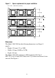
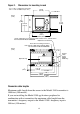
Figure 1. Space requirements for proper ventilation 1 U = 1 HE = 1.750 inches (44,5 mm) 3 U (3 HE) 1 U (1 HE) 3 U (3 HE) 1 U (1 HE) 3 U (3 HE) Dimensions The Model 3300/3500 has the following dimensions (see Figure 2, page 4): • Height: 128 mm (3 U or 3 HE) • Width: 142 mm (28 HP or 28 TE) • Depth: 160 mm The Model 3300/3500 conforms to DIN standard 41494, Part 5 (IEC 297-3) for 19-inch (486,2 mm) racks. Up to three enclosures fit into one rack. See Figure 1.
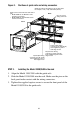
Figure 2. Dimensions for mounting in rack 1 U = 1 HE = 1.750 inches (44,5 mm) 1 HP = 1 TE = 0.200 inch (5,1 mm) 25 HP (25 TE) 4 x M2.5x11 inches (mm) 3U (3 HE) 5 1/16 (128,5) 4 13/16 (122,5) 5.6 (142,2) 28 HP (28 TE) 19-inch (486,2 mm) rack conforms to DIN 41494, Part 5, and IEC 297-3. Not included with Model 3300/3500. Optional screw terminal Rear rail for mounting connectors that conform to DIN 41612 and IEC 603-2. Not included with Model 3300/3500.
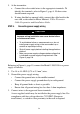
STEP 2. Installing guide rails and wiring connectors Guide rails Positions of guide rails and wiring connectors are indicated in Figure 3, page 6. Centers of guide rails should be 27 HP (27 TE) apart, for example, at 1 HP (TE) and 28 HP (TE). Wiring connectors The applications platform is shipped with a solder-tail or screw-type connector for input/output wiring, a keyed solder-tail or screw-type connector for sensor wiring (Model 3500 only), and a plug-in connector for power supply wiring.
Figure 3. Positions of guide rails and wiring connectors Guide rail centers should be 27 HP (27 TE) apart; for example, 1 HP (1 TE) and 28 HP (28 TE) Install screws and connectors from front of rack. • Model 3500 has six M2.5x8 screws and three connectors. • Model 3300 has four M2.5x8 screws and two connectors. Back Keys on sensor wiring connector Front M2.
STEP 4. Connecting input and output wiring Connect input and output wiring to the appropriate terminals on the input/output wiring connector, which is the far right connector. Refer to Table 1 and to the card that is inserted into the sleeve on the top panel (shown in Figure 4). • Use 24 to 16 AWG (0,25 to 1,5 mm2) twisted-pair shielded wire. • Ground the shields at a single point only. Table 1.
1. Identify the components shown in Figure 5. Figure 5. Sensor cable to Model 3500 Model 3500 Keyed sensor wiring connector (see Figure 3, page 6) 9-wire cable from sensor black (drain wires from all wire sets) brown red yellow violet green blue brown c 2 a c 4 a c 6 a c 8 a c 10 a c 12 a green white c 14 a blue gray c 18 a orange yellow violet c 22 a black (drains) orange white gray red c 16 a c 20 a c 24 a c 26 a c 28 a c 30 a c 32 a 2.
5. At the transmitter: a. Connect the color-coded wires to the appropriate terminals. To identify the terminals, refer to Figure 5, page 8. No bare wires should remain exposed. b. If using shielded or armored cable, connect the cable braid to the rear stud, as described in Micro Motion’s 9-Wire Flowmeter Cable Preparation and Installation Guide. STEP 6. Connecting power supply wiring CAUTION Improper wiring installation can cause device failure or measurement error.
Figure 6.
©2003, Micro Motion, Inc. All rights reserved. P/N 3300995, Rev. C *3300995* Visit us on the Internet at www.micromotion.com Micro Motion Inc.