Configuration and Use Manual P/N MMI-20007739, Rev.
©2008, Micro Motion, Inc. All rights reserved. ELITE and ProLink are registered trademarks, and MVD and MVD Direct Connect are trademarks of Micro Motion, Inc., Boulder, Colorado. Micro Motion is a registered trade name of Micro Motion, Inc., Boulder, Colorado. The Micro Motion and Emerson logos are trademarks and service marks of Emerson Electric Co. All other trademarks are property of their respective owners.
Contents Chapter 1 Before You Begin . . . . . . . . . . . . . . . . . . . . . . . . . . . . . . . . . . . . . 1 1.1 1.2 1.3 1.4 1.5 1.6 1.7 1.8 1.9 1.10 Chapter 2 Overview . . . . . . . . . . . . . . . . . . . . . . . . . . . . . . . . . . . . . . . . . . . . . . . . . . . . . . . . . . . 7 Setting the DeviceNet node address and baud rate . . . . . . . . . . . . . . . . . . . . . . . . . . 7 Bringing the transmitter online . . . . . . . . . . . . . . . . . . . . . . . . . . . . . . . . . . . . . . . . .
Contents Chapter 5 Using a DeviceNet Tool . . . . . . . . . . . . . . . . . . . . . . . . . . . . . . . . 21 5.1 5.2 5.3 5.4 5.5 Chapter 6 6.3 Overview . . . . . . . . . . . . . . . . . . . . . . . . . . . . . . . . . . . . . . . . . . . . . . . . . . . . . . . . . . Characterizing the flowmeter . . . . . . . . . . . . . . . . . . . . . . . . . . . . . . . . . . . . . . . . . . 6.2.1 When to characterize. . . . . . . . . . . . . . . . . . . . . . . . . . . . . . . . . . . . . . . . 6.2.
Contents Chapter 8 Optional Configuration . . . . . . . . . . . . . . . . . . . . . . . . . . . . . . . . 55 8.1 8.2 8.3 8.4 8.5 8.6 8.7 8.8 8.9 8.10 8.11 8.12 8.13 8.14 Chapter 9 Overview . . . . . . . . . . . . . . . . . . . . . . . . . . . . . . . . . . . . . . . . . . . . . . . . . . . . . . . . . . Configuring volume flow measurement for gas . . . . . . . . . . . . . . . . . . . . . . . . . . . . . 8.2.1 Using ProLink II . . . . . . . . . . . . . . . . . . . . . . . . . . . . . . . . . . . . .
Contents Chapter 10 Measurement Performance . . . . . . . . . . . . . . . . . . . . . . . . . . . . . 89 10.1 10.2 10.3 10.4 10.5 10.6 10.7 Overview . . . . . . . . . . . . . . . . . . . . . . . . . . . . . . . . . . . . . . . . . . . . . . . . . . . . . . . . . . 89 Meter validation, meter verification, and calibration . . . . . . . . . . . . . . . . . . . . . . . . . 89 10.2.1 Meter verification . . . . . . . . . . . . . . . . . . . . . . . . . . . . . . . . . . . . . . . . . . . 90 10.2.
Contents Appendix A Default Values and Ranges . . . . . . . . . . . . . . . . . . . . . . . . . . . . 131 A.1 A.2 Overview . . . . . . . . . . . . . . . . . . . . . . . . . . . . . . . . . . . . . . . . . . . . . . . . . . . . . . . . . 131 Most frequently used defaults and ranges . . . . . . . . . . . . . . . . . . . . . . . . . . . . . . . 131 Appendix B Menu Flowcharts . . . . . . . . . . . . . . . . . . . . . . . . . . . . . . . . . . . 135 B.1 B.2 Overview . . . . . . . . . . . . . . . . . . . . .
vi Micro Motion® Model 2400S Transmitters for DeviceNet™
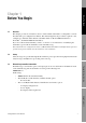
1.1 Before You Begin Chapter 1 Before You Begin Overview This chapter provides an orientation to the use of this manual, and includes a configuration overview flowchart and a pre-configuration worksheet. This manual describes the procedures required to start, configure, use, maintain, and troubleshoot the Micro Motion® Model 2400S transmitter for DeviceNet™ (the Model 2400S DN transmitter). Startup If you do not know what transmitter you have, see Section 1.
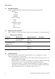
Before You Begin 1.4 DeviceNet functionality The Model 2400S DN transmitter implements the following DeviceNet functionality: • • • 1.5 Baud rates: - 125 kBaud - 250 kBaud - 500 kBaud I/O slave messaging: - Polling - Cyclic Configuration methods: - Hardware switches - EDS - Custom software Determining version information Table 1-1 lists the version information that you may need and describes how to obtain the information.
Before You Begin In this manual: Basic information on using the transmitter’s user interface is provided in Chapter 3. • Basic information on using ProLink II or Pocket ProLink, and connecting ProLink II or Pocket ProLink to your transmitter, is provided in Chapter 4. For more information, see the ProLink II or Pocket ProLink manual, available on the Micro Motion web site (www.micromotion.com). • Basic information on using a customer-supplied DeviceNet tool is provided in Chapter 5.
Before You Begin Figure 1-1 Configuration overview Chapter 1 Before You Begin Fill out pre-configuration worksheet Chapter 2 Flowmeter Startup Start the flowmeter Configure DeviceNet communications parameters (optional) Chapter 8 Optional Configuration Chapter 9 Pressure Compensation and Temperature Compensation Configure volume flow measurement for gas Configure cutoffs Configure temperature compensation (optional) Configure damping Chapter 10 Measurement Performance Configure flow direction Zer
Before You Begin Transmitter ____________________________ Item Configuration data Before You Begin Pre-configuration worksheet Transmitter model number ______________________________________ Core processor (transmitter) software revision ______________________________________ DeviceNet node address ______________________________________ DeviceNet baud rate ______________________________________ Measurement units Mass flow ______________________________________ Volume flow __________________________
Before You Begin 1.10 Micro Motion customer service For customer service, phone the support center nearest you: • In the U.S.A., phone 800-522-MASS (800-522-6277) (toll-free) • In Canada and Latin America, phone +1 303-527-5200 • In Asia: • - In Japan, phone 3 5769-6803 - In other locations, phone +65 6777-8211 (Singapore) In Europe: - In the U.K., phone 0870 240 1978 (toll-free) - In other locations, phone +31 (0) 318 495 555 (The Netherlands) Customers outside the U.S.A.
2.1 Before You Begin Chapter 2 Flowmeter Startup Overview This chapter describes the following procedures: Setting the DeviceNet node address and baud rate – see Section 2.2 • Bringing the transmitter online – see Section 2.3 Setting the DeviceNet node address and baud rate Startup 2.2 • The default node address for the Model 2400S DN transmitter is 63. The default baud rate is 125 kBaud.
Flowmeter Startup 3. Insert an appropriate DeviceNet cable into the connector on the transmitter. When the transmitter receives power, it will automatically perform diagnostic routines, and the module LED flashes red and green. When the flowmeter has completed its power-up sequence, the status LED will show a solid green. See Section 7.4 for information on LED behavior. If the status LED exhibits different behavior, an alarm condition is present. See Section 7.5. 4.
3.1 Before You Begin Chapter 3 Using the Transmitter User Interface Overview This chapter describes the user interface of the Model 2400S DN transmitter. The following topics are discussed: Transmitters without or with display – see Section 3.2 • Removing and replacing the transmitter housing cover – see Section 3.3 • Using the Scroll and Select optical switches – see Section 3.4 • Using the display – see Section 3.5 Startup 3.
Using the Transmitter User Interface Figure 3-1 User interface – Transmitters without display Digital communications hardware switches Zero button Status LED Module LED Network LED Service port clips Figure 3-2 User interface – Transmitters with display Digital communications hardware switches LCD panel Current value Status LED Process variable Module LED FLOW Unit of measure 3.
Using the Transmitter User Interface For information on: Using the digital communications hardware switches, see Section 8.10. • Using the LEDs, see Section 7.4. • Making a service port connection, see Chapter 4. • Using the zero button, see Section 10.5. Before You Begin 3.3 • Removing and replacing the transmitter housing cover For some procedures, you must remove the transmitter housing cover. To remove the transmitter housing cover: 1.
Using the Transmitter User Interface 3.5 Using the display Note: This section applies only to transmitters with a display. The display can be used to view process variable data or to access the transmitter menus for configuration or maintenance. 3.5.1 Display language The display can be configured for the following languages: • English • French • Spanish • German Due to software and hardware restrictions, some English words and terms may appear in the non-English display menus.
Using the Transmitter User Interface 3.5.3 Using display menus Before You Begin Note: The display menu system provides access to basic transmitter functions and data. It does not provide access to all functions and data. To access all functions and data, use either ProLink II or a customer-supplied DeviceNet tool. To enter the display menu system, see the flowchart shown in Figure 3-3.
Using the Transmitter User Interface 3.5.4 Display password Some of the display menu functions, such as accessing the off-line menu, can be protected by a display password. For information about enabling and setting the display password, refer to Section 8.9. If a password is required, the word CODE? appears at the top of the password screen. Enter the digits of the password one at a time by using Scroll to choose a number and Select to move to the next digit.
Using the Transmitter User Interface To change from decimal to exponential notation (see Figure 3-5): 2. Scroll to E, then Select. The display changes to provide two spaces for entering the exponent. 3. To enter the exponent: a. Select until the desired digit is flashing. b. Scroll to the desired value. You can enter a minus sign (first position only), values between 0 and 3 (for the first position in the exponent), or values between 0 and 9 (for the second position in the exponent). Before You Begin 1.
16 Micro Motion® Model 2400S Transmitters for DeviceNet™
4.1 Before You Begin Chapter 4 Connecting with ProLink II or Pocket ProLink Software Overview ProLink II is a Windows-based configuration and management tool for Micro Motion transmitters. It provides access to most transmitter functions and data. Pocket ProLink is a version of ProLink II that runs on a Pocket PC. • Requirements – see Section 4.2 • Configuration upload/download – see Section 4.3 • Connecting to a Model 2400S DN transmitter – see Section 4.
Connecting with ProLink II or Pocket ProLink Software 4.4 Connecting to a Model 2400S DN transmitter To connect to the Model 2400S DN transmitter using ProLink II or Pocket ProLink, you must use a service port connection. 4.4.1 Connection options The service port can be accessed via the service port clips or the IrDA port. The service port clips have priority over the IrDA port: • If there is an active connection via the service port clips, access via the IrDA port is disabled.
Connecting with ProLink II or Pocket ProLink Software Before You Begin WARNING Removing the transmitter housing cover in a hazardous area can cause an explosion. Because the transmitter housing cover must be removed to connect to the service port clips, the service port clips should be used only for temporary connections, e.g., for configuration or troubleshooting purposes. When the transmitter is in an explosive atmosphere, use a different method to connect to your transmitter.
Connecting with ProLink II or Pocket ProLink Software 4.4.4 Connecting via the IrDA port Note: The IrDA port is typically used with Pocket ProLink. To use the IrDA port with ProLink II, a special device is required; the IrDA port built into many laptop PCs is not supported. For more information on using the IrDA port with ProLink II, contact Micro Motion customer service. To connect to the service port via the IrDA port: 1. Ensure that the IrDA port is enabled (see Section 8.10.6).
5.1 Using a DeviceNet Tool Chapter 5 Using a DeviceNet Tool Overview A customer-supplied DeviceNet tool can be used to communicate with the Model 2400S DN transmitter. This chapter provides basic information on using a customer-supplied DeviceNet tool. 5.2 Connecting to the Model 2400S DN transmitter To connect to the Model 2400S DN transmitter: 1.
Using a DeviceNet Tool For complete documentation of the Model 2400S DN transmitter’s device profile, including input and output assemblies, see the manual entitled Micro Motion Model 2400S Transmitters for DeviceNet: Device Profile. 5.4 Using a DeviceNet tool Micro Motion supplies an Electronic Data Sheet (EDS) for the Model 2400S transmitter. The EDS file is named MMI2400S-MassFlow.eds. The EDS presents the device profile in a format designed to be read and interpreted by other devices.
Using a DeviceNet Tool Default assemblies The default assemblies used by the Model 2400S DN transmitter are listed and described in Table 5-1. To change the default assemblies, see the flowchart in Figure 5-1.
24 Micro Motion® Model 2400S Transmitters for DeviceNet™
6.1 Using a DeviceNet Tool Chapter 6 Required Transmitter Configuration Overview This chapter describes the configuration procedures that are usually required when a transmitter is installed for the first time. The following procedures are discussed: Characterizing the flowmeter – see Section 6.2 • Configuring measurement units – see Section 6.3 This chapter provides basic flowcharts for each procedure.
Required Transmitter Configuration Table 6-1 Sensor calibration parameters Sensor type Parameter T-Series Other K1 ✓ ✓ K2 ✓ ✓ FD ✓ ✓ D1 ✓ ✓ D2 ✓ ✓ Temp coeff (DT)(1) ✓ ✓ ✓(2) Flowcal FCF ✓ FTG ✓ FFQ ✓ DTG ✓ DFQ1 ✓ DFQ2 ✓ (1) On some sensor tags, shown as TC. (2) See the section entitled “Flow calibration values.” Figure 6-1 Sample calibration tags T-Series Other sensors 19.0005.13 12500142864.44 12502.000 0.0010 14282.000 0.9980 4.
Required Transmitter Configuration • With ProLink II, enter the concatenated 10-character string exactly as shown, including the decimal points. For example, using the Flow Cal value from Figure 6-1, enter 19.0005.13. • With a DeviceNet tool, enter the two factors separately, i.e., enter a 6-character string and a 4-character string. Include the decimal point in both strings. For example, using the Flow Cal value from Figure 6-1: 6.2.3 - Enter 19.000 for the flow calibration factor. - Enter 5.
Required Transmitter Configuration 6.3 Configuring the measurement units For each process variable, the transmitter must be configured to use the measurement unit appropriate to your application. To configure measurement units for process variables, see the menu flowcharts in Figure 6-3. For details on measurement units for each process variable, see Sections 6.3.1 through 6.3.4.
Required Transmitter Configuration Configuring measurement units ProLink II Using a DeviceNet Tool Figure 6-3 Display Off-line maint > Off-line config ProLink > Configuration Flow Units Density Mass Temperature Vol (or GSV) Pressure Density Required Configuration Temperature DeviceNet tool Pressure Volume flow unit (liquid) Class: Analog Input Point Object (0x0A) Instance: 2 Attribute ID: 102 Value: See Table 6-3 Service: Set Density unit Class: Analog Input Point Object (0x0A) Instance:
Required Transmitter Configuration 6.3.1 Mass flow units The default mass flow measurement unit is g/s. See Table 6-2 for a complete list of mass flow measurement units.
Required Transmitter Configuration Volume flow measurement units – Liquid continued Using a DeviceNet Tool Table 6-3 Volume flow unit Display ProLink II DeviceNet tool CUFT/D ft3/day ft3/day 0x0816 Cubic feet per day M3/S m3/sec m3/s 0x1405 Cubic meters per second M3/MIN m3/min m3/min M3/H m3/hr DeviceNet code Unit description 0x080F Cubic meters per minute 3 m /hr 0x0810 Cubic meters per hour 3 M3/D m3/day m /day 0x0811 Cubic meters per day USGPS US gal/sec gal/s 0x14
Required Transmitter Configuration Table 6-4 Volume flow measurement units – Gas continued Volume flow unit Display ProLink II DeviceNet tool DeviceNet code Unit description NLPM NLPM Nml l/min 0x1401 Normal liter per minute NLPH NLPH Nml l/hr 0x083E Normal liter per hour NLPD NLPD Nml l/day SCFS SCFS SCFM SCFM SCFH SCFH SCFD SCFD SM3/S Sm3/S 0x083F Normal liter per day 3 0x0831 Standard cubic feet per second 3 0x0832 Standard cubic feet per minute 3 0x0833 Standard
Required Transmitter Configuration Temperature units Using a DeviceNet Tool 6.3.4 The default temperature measurement unit is °C. See Table 6-6 for a complete list of temperature measurement units.
Required Transmitter Configuration Table 6-7 Pressure measurement units continued Pressure unit Display ProLink II DeviceNet tool DeviceNet code Unit description MPA megapascals MPA 0x085B Megapascals TORR Torr @ 0C torr 0x1301 Torr @ 0 °C ATM atms ATM 0x130B Atmospheres 34 Micro Motion® Model 2400S Transmitters for DeviceNet™
7.1 Using a DeviceNet Tool Chapter 7 Using the Transmitter Overview This chapter describes how to use the transmitter in everyday operation. The following topics and procedures are discussed: Recording process variables – see Section 7.2 • Viewing process variables – see Section 7.3 • Viewing transmitter status and alarms – see Section 7.5 • Handling status alarms – see Section 7.6 • Viewing and controlling the totalizers and inventories – see Section 7.
Using the Transmitter 7.3 Viewing process variables Process variables include measurements such as mass flow rate, volume flow rate, mass total, volume total, temperature, and density. You can view process variables with the display (if your transmitter has a display), ProLink II, or a DeviceNet tool. Note: If the petroleum measurement application is enabled, two of the API process variables are averages: Batch Weighted Average Density and Batch Weighted Average Temperature.
Using the Transmitter 7.3.3 With a DeviceNet tool There are two methods that can be used to view process variables with a DeviceNet tool: You can execute Gets to read the current values of individual process variables from the appropriate objects. Table 7-1 lists the most commonly used process variables, by class, instance, attribute, and data type. For more information, see the manual entitled Micro Motion Model 2400S Transmitters for DeviceNet: Device Profile.
Using the Transmitter Table 7-1 Process data in DeviceNet objects continued Class (1) API Object (0x69) Enhanced Density Object (0x6A)(2) Instance Attribute ID Data type Description 1 1 REAL Temperature-corrected density 2 REAL Temperature-corrected (standard) volume flow 3 REAL Temperature-corrected (standard) volume total 4 REAL Temperature-corrected (standard) volume inventory 5 REAL Batch weighted average density 6 REAL Batch weighted average temperature 7 REAL CTL 1 REA
Using the Transmitter Summary of input assemblies continued Data description Size (bytes) Data type Description 6 • Status • Mass flow • Mass total • Mass inventory • Temperature • Density 21 • BOOL • REAL • REAL • REAL • REAL • REAL Mass flow, mass totals, and other process variables 7(1) • Status • Volume flow • Volume total • Volume inventory • Temperature • Density 21 • BOOL • REAL • REAL • REAL • REAL • REAL Volume flow, volume totals, and other process variables 8(2) • Status • Mass fl
Using the Transmitter Table 7-2 Summary of input assemblies continued Instance ID Data description Size (bytes) Data type Description 16(1)(3) • Status • API temperature-corrected density • API temperature-corrected volume flow • API temperature-corrected volume inventory • API average temperature-corrected density • API average temperature 21 • BOOL • REAL • REAL • REAL • REAL • REAL Petroleum measurement application 17(1)(4) • Status • Mass flow • Volume flow • Temperature • Enhanced density
Using the Transmitter Summary of input assemblies continued Data description Size (bytes) Data type Description 24(1)(4) • Status • Mass flow • Volume flow • Density • Enhanced density reference density • Enhanced density standard volume flow 21 • BOOL • REAL • REAL • REAL • REAL • REAL Enhanced density application 25(4) • Status • Mass flow • Temperature • Density • Enhanced density reference density • Enhanced density concentration 21 • BOOL • REAL • REAL • REAL • REAL • REAL Enhanced densit
Using the Transmitter Table 7-3 Module LED states, definitions, and recommendations Module LED state Definition Recommendations Off No power Check the connection to the DeviceNet network. Solid green No processor faults No action required. Flashing green Needs DeviceNet configuration; may be in Standby state Indicates an A006 alarm. Characterization parameters are missing. See Section 6.2. Solid red Non-recoverable fault Power cycle the transmitter.
Using the Transmitter Transmitter status LED Status LED state Alarm priority Definition Green No alarm Normal operating mode Flashing yellow A104 alarm Zero or calibration in progress Solid yellow Low severity (information) alarm • Alarm condition: will not cause measurement error • Digital communications report process data Red High severity (fault) alarm • Alarm condition: will cause measurement error • Digital communications go to configured fault indicator (see Section 8.10.7) 7.5.
Using the Transmitter In addition, the transmitter maintains alarm history for the 50 most recent alarm occurrences. Alarm history includes: • The alarm code • The “alarm active” timestamp • The “alarm inactive” timestamp • The “alarm acknowledged” timestamp When the transmitter detects an alarm condition, it checks the severity level of the specific alarm and performs the actions described in Table 7-6.
Using the Transmitter Viewing and acknowledging alarms with the display Using a DeviceNet Tool Figure 7-1 Scroll and Select simultaneously for 4 seconds SEE ALARM Select ACK ALL(1) Yes (1) This screen is displayed only if the ACK ALL function is enabled (see Section 8.9.3) and there are unacknowledged alarms. No Select Scroll Required Configuration EXIT Select Scroll Active/ unacknowledged alarms? Yes No Alarm code Select Scroll ACK EXIT Yes Select 7.6.
Using the Transmitter In the Status window: • Alarms are organized into three categories: Critical, Informational, and Operational. Each category is displayed on a separate panel. • If one or more alarms is active on a panel, the corresponding tab is red. • On a panel, a green LED indicates “inactive” and a red LED indicates “active.” Note: The location of alarms on the Status panels is pre-defined, and is not affected by alarm severity. To use the Status window: 1. Click ProLink > Status. 2.
Using the Transmitter Using a DeviceNet Tool To view information about a single alarm: 1. Execute a Set for Attribute 18, specifying the code for the alarm you want to check. 2. Execute a Get for Attribute 42, and interpret the data using the following codes: • 0x00 = Acknowledged and cleared • 0x01 = Active and acknowledged • 0x10 = Not acknowledged, but cleared • 0x11 = Not acknowledged, and active 3.
Using the Transmitter 7.7.1 Viewing current values for totalizers and inventories You can view current values for the totalizers and inventories with the display (if your transmitter has a display), ProLink II, or a DeviceNet tool. With the display You cannot view current totalizer or inventory values with the display unless the display has been configured to show them. See Section 8.9.5. To view a totalizer or inventory value, refer to Figure 7-2 and: 1.
Using the Transmitter Using a DeviceNet Tool With ProLink II To view current totals for the totalizers and inventories with ProLink II: 1. Click ProLink. 2. Select Process Variables, API Process Variables, or ED Process Variables. With a DeviceNet tool To view current totals for the totalizers and inventories with a DeviceNet tool, see Section 7.3.3. 7.7.2 Controlling totalizers and inventories Specific starting, stopping, and resetting functionality depends on the tool you are using.
Using the Transmitter With ProLink II The totalizer and inventory control functions available with ProLink II are listed in Table 7-7. Note the following: • ProLink II does not support separate resetting of the API volume totalizer and API volume inventory. To reset these, you must reset all totalizers or all inventories. • By default, the ability to reset inventories from ProLink II is disabled. To enable it: a. Click View > Preferences. b. Check the Enable Inventory Totals Reset checkbox. c.
Using the Transmitter Using a DeviceNet Tool To reset an individual totalizer or inventory: 1. Click ProLink > Totalizer Control or ProLink > ED Totalizer Control (if the enhanced density application is enabled). 2. Click the appropriate button (e.g., Reset Mass Total, Reset Volume Inventory, Reset Net Mass Total).
Using the Transmitter Table 7-8 Totalizer and inventory control with a DeviceNet tool using explicit write continued To accomplish this Use this device profile data Reset all inventories Analog Input Point Object (0x0A) Instance: 0 Attribute ID: 102 Service: Set Value: 1 Reset mass totalizer Analog Input Point Object (0x0A) Instance: 1 Service: Reset Total (0x32) Reset mass inventory Analog Input Point Object (0x0A) Instance: 1 Service: Reset Inventory (0x33) Reset liquid volume totalizer Analog
Using the Transmitter Output assemblies used for totalizer and inventory control Instance ID Data description Size (bytes) Data type 53 • Start/stop all totalizers and inventories 1 • BOOL 54 • Reset all totalizer values 1 • BOOL 55 • Reset all inventory values 1 • BOOL 56 • Start/stop all totalizers and inventories • Reset all totalizer values 2 • BOOL • BOOL 57 • Start/stop all totalizers and inventories • Reset all totalizer values • Reset all inventory values 3 • BOOL • BOOL • B
54 Micro Motion® Model 2400S Transmitters for DeviceNet™
8.1 Using a DeviceNet Tool Chapter 8 Optional Configuration Overview This chapter describes transmitter configuration parameters that may or may not be used, depending on your application requirements. For required transmitter configuration, see Chapter 6. Note: All ProLink II procedures provided in this chapter assume that you have established communication between ProLink II and the Model 2400S DN transmitter and that you are complying with all applicable safety requirements.
Optional Configuration Table 8-1 Configuration map continued Tool Topic Subtopic ProLink II DeviceNet tool Display Section Display(1) Update period ✓ ✓ ✓ 8.9.1 Display language ✓ ✓ ✓ 8.9.2 Totalizer start/stop ✓ ✓ ✓ 8.9.
Optional Configuration Using a DeviceNet Tool Only one type of volume flow measurement can be performed at a time (i.e., if liquid volume flow measurement is enabled, gas standard volume flow measurement is disabled, and vice versa). Different sets of volume flow measurement units are available, depending on which type of volume flow measurement is enabled (see Tables 6-3 and 6-4). If you will use a gas standard volume flow unit, additional configuration is required.
Optional Configuration 5. Click Next. 6. Verify the reference temperature and reference pressure. If these are not appropriate for your application, click the Change Reference Conditions button and enter new values for reference temperature and reference pressure. 7. Click Next. The calculated standard density value is displayed. • If the value is correct, click Finish. The value will be written to transmitter configuration. • If the value is not correct, click Back and modify input values as required.
Optional Configuration Cutoff default values Cutoff type Default Comments Mass flow 0.0 g/s Recommended setting: 5% of the sensor’s rated maximum flowrate Liquid volume flow 0.0 L/s Limit: the sensor’s flow calibration factor in liters per second, multiplied by 0.2 Gas standard volume flow 0.0 No limit Density 0.2 g/cm3 Range: 0.0–0.5 g/cm3 Using a DeviceNet Tool Table 8-2 To configure cutoffs: • Using ProLink II, see Figure B-2.
Optional Configuration Table 8-3 Valid damping values Process variable Valid damping values Flow (mass and volume) 0, 0.04, 0.08, 0.16, ... 40.96 Density 0, 0.04, 0.08, 0.16, ... 40.96 Temperature 0, 0.6, 1.2, 2.4, 4.8, ... 76.8 To configure damping values: • Using ProLink II, see Figure B-2. • Using a DeviceNet tool, see Tables C-1, C-3, and C-4. Note: This functionality is not available via the display menus. 8.4.
Optional Configuration Effect of flow direction on totalizers and flow values Using a DeviceNet Tool Table 8-4 Forward flow(1) Flow direction value Flow totals Flow values Forward only Increase Positive Reverse only No change Positive Bidirectional Increase Positive Absolute value Increase Positive(2) Negate/Forward only No change Negative Negate/Bidirectional Decrease Negative Reverse flow(3) Flow totals Flow values Forward only No change Negative Reverse only Increase Negat
Optional Configuration 3. Assign a process variable to the event (Attribute 10). 4. Specify the event’s setpoint(s) – the value(s) at which the event will occur or switch state (ON to OFF, or vice versa). • If Event Type is High or Low, only Setpoint A is used (Attribute 8) • If Event Type is In Range or Out of Range, both Setpoint A and Setpoint B (Attributes 9 and 10) are required. 5. Assign the event to an action or actions, if desired. Possible actions are listed in Table 8-6.
Optional Configuration Event actions continued ProLink II label Display label DeviceNet code Description Reset all totals RESET ALL 8 Resets the value of all totalizers to 0 Start/stop all totalization START STOP 9 If totalizers are running, stops all totalizers If totalizers are not running, starts all totalizers Increment current ED curve INCR CURVE 18 Changes the active enhanced density curve from 1 to 2, from 2 to 3, etc.
Optional Configuration 8.6.2 Checking and reporting event status There are several ways that event status can be determined: • ProLink II automatically displays event information on the Informational panel of the Status window. • The status of each event is stored in the Diagnostics Object (0x66), Instance 1, Attribute 11. For more information, see Table C-7, or see the manual entitled Micro Motion Model 2400S Transmitters for DeviceNet: Device Profile. 8.6.
Optional Configuration • A slug flow alarm is posted immediately. • During the slug duration period, the transmitter holds the mass flow rate at the last measured pre-slug value, independent of the mass flow rate measured by the sensor. The reported mass flow value is set to this value, and all internal calculations that include mass flow rate will use this value.
Optional Configuration Some alarms can be reclassified. For example: • The default severity level for Alarm A020 (calibration factors unentered) is Fault, but you can reconfigure it to either Informational or Ignore. • The default severity level for Alarm A102 (drive over-range) is Informational, but you can reconfigure it to either Ignore or Fault. For a list of all status alarms and default severity levels, see Table 8-8.
Optional Configuration Status alarms and severity levels continued Alarm code ProLink II message Default severity Configurable? Affected by fault timeout? A116 API: Temperature Outside Standard Range Info Yes No A117 API: Density Outside Standard Range Info Yes No A120 ED: Unable to Fit Curve Data Info No No A121 ED: Extrapolation Alarm Info Yes No A131 Meter Verification/Outputs at Last Value Info Yes No A132 Simulation Mode Active Info Yes No A133 PIC UI EEPROM Error
Optional Configuration Table 8-9 Display functions Parameter Enabled (shown) Disabled (hidden) Totalizer start/stop Operators can start or stop totalizers using the display. Operators cannot start or stop totalizers using the display. Totalizer reset Operators can reset the mass and volume totalizers using the display. Operators cannot reset the mass and volume totalizers using the display. Auto scroll(1) The display automatically scrolls through each process variable at a configurable rate.
Optional Configuration • Using ProLink II, see Figure B-3. • Using a DeviceNet tool, see Table C-9. 8.9.5 Using a DeviceNet Tool In addition, if you are using ProLink II or a DeviceNet tool, you can control the intensity of the backlight. You can specify any value between 0 and 63; the higher the value, the brighter the backlight. To control the intensity of the backlight: Configuring the display variables and display precision The display can scroll through up to 15 process variables in any order.
Optional Configuration 8.10 Configuring digital communications The digital communications parameters control how the transmitter will communicate using digital communications. The following digital communications parameters can be configured: • DeviceNet node address (MAC ID) • DeviceNet baud rate • DeviceNet configurable input assembly • Modbus address • Modbus ASCII support • IrDA port usage • Digital communications fault action • Fault timeout 8.10.
Optional Configuration DeviceNet baud rate The default baud rate for the Model 2400S DN transmitter is 125 kBaud. Valid baud rates are listed in Table 8-11. The baud rate can be set using a digital communications hardware switch or a DeviceNet tool. If the device cannot determine what its baud rate should be, it defaults to 500 kBaud. Note: You cannot set the baud rate from ProLink II or the display. To set the baud rate using the digital communications hardware switch: Using a DeviceNet Tool 8.10.2 1.
Optional Configuration The Assembly Object is used to configure the configurable input assembly. See the flowchart in Figure 8-2. Figure 8-2 8.10.
Optional Configuration To enable or disable Modbus ASCII support: • Using ProLink II, see Figure B-2. • Using the display menus, see Figure B-6. 8.10.6 IrDA port usage Using a DeviceNet Tool The primary reason to disable Modbus ASCII support is to allow a wider range of Modbus addresses for the service port. The IrDA port on the display can be enabled or disabled. If enabled, it can be set for read-only or read/write access. To enable or disable the IrDA port: Using ProLink II, see Figure B-2.
Optional Configuration To configure digital communications fault action: • Using ProLink II, see Figure B-2. • Using a DeviceNet tool, see Table C-7. Note: This functionality is not available via the display menus. 8.10.8 Fault timeout By default, the transmitter activates the digital communications fault action as soon as the fault is detected. The fault timeout allows you to delay the digital communications fault action for a specified interval, for certain faults only.
Optional Configuration Configuring sensor parameters The sensor parameters are used to describe the sensor component of your flowmeter. They are not used in transmitter processing, and are not required. The following sensor parameters can be changed: • Serial number (can be set only once) • Sensor material • Sensor liner material • Sensor flange type Using a DeviceNet Tool 8.12 To configure sensor parameters: • Using ProLink II, see Figure B-2. • Using a DeviceNet tool, see Table C-8.
Optional Configuration API reference tables Reference tables are organized by reference temperature, CTL derivation method, liquid type, and density unit. The table selected here controls all the remaining options. • • • • 76 Reference temperature: - If you specify a 5x, 6x, 23x, or 24x table, the default reference temperature is 60 °F, and cannot be changed. - If you specify a 53x or 54x table, the default reference temperature is 15 °C.
Optional Configuration Using a DeviceNet Tool Table 8-14 summarizes these options. Table 8-14 API reference temperature tables Density unit and range Table CTL derivation method Base temperature Degrees API 5A Method 1 60 °F, non-configurable 0 to +100 5B Method 1 60 °F, non-configurable 0 to +85 5D Method 1 60 °F, non-configurable –10 to +40 23A Method 1 60 °F, non-configurable 0.6110 to 1.0760 23B Method 1 60 °F, non-configurable 0.6535 to 1.
Optional Configuration For the temperature value to be used in CTL calculation, you can use the temperature data from the sensor, or you can configure external temperature compensation to use either a static temperature value or temperature data from an external temperature device. 8.14 • To use temperature data from the sensor, no action is required. • To configure external temperature compensation, see Section 9.3.
Optional Configuration Name Description Density unit Temperature unit HFCS 42 Curve represents a hydrometer scale for HFCS 42 (high fructose corn syrup) solutions that indicates the percent by mass of HFCS in solution. g/cm3 °C HFCS 55 Curve represents a hydrometer scale for HFCS 55 (high fructose corn syrup) solutions that indicates the percent by mass of HFCS in solution.
Optional Configuration Table 8-17 Derived variables and available process variables continued Available process variables Density at Standard reference volume temperature flow rate Specific gravity Concentration Volume Conc (SG) Volume concentration derived from specific gravity The percent volume of solute or of material in suspension in the total solution, derived from specific gravity ✓ ✓ ✓ ✓ Conc (Dens) Concentration derived from reference density The mass, volume, weight, or number of moles of
Optional Configuration Configuring the enhanced density application – DeviceNet tool Class: Analog Input Point Object (0x0A) Instance: 3 Attribute ID: 102 Value: See Table 6-5 Service: Set Set transmitter temperature measurement unit to match curve unit · For standard curves, see Table 8-16 · For custom curves, see the information provided with the curve Class: Analog Input Point Object (0x0A) Instance: 4 Attribute ID: 102 Value: See Table 6-6 Service: Set Set derived variable · For standard curves, us
82 Micro Motion® Model 2400S Transmitters for DeviceNet™
Overview This chapter describes the following procedures: • Configuring pressure compensation – see Section 9.2 • Configuring external temperature compensation – see Section 9.3 • Obtaining external pressure or temperature data – see Section 9.4 Note: All ProLink II procedures provided in this chapter assume that you have established communication between ProLink II and the Model 2400S DN transmitter and that you are complying with all applicable safety requirements.
Pressure Compensation and Temperature Compensation 9.2.2 Pressure correction factors When configuring pressure compensation, you must provide the flow calibration pressure – the pressure at which the flowmeter was calibrated (which therefore defines the pressure at which there will be no effect on the calibration factor). Enter 20 PSI unless the calibration document for your sensor indicates a different calibration pressure.
Pressure Compensation and Temperature Compensation Figure 9-2 Configuring pressure compensation with a DeviceNet tool (1) Pressure measurement unit must be configured to match pressure unit used by external device. See Section 6.3. Set flow calibration (2) See Section 9.4.
Pressure Compensation and Temperature Compensation There are two ways to configure external temperature compensation: • If the operating temperature is a known static value, you can configure that value in the transmitter. • If the operating temperature varies significantly, you must write a temperature value to the transmitter at appropriate intervals, using an appropriate output assembly. See Section 9.4.
Pressure Compensation and Temperature Compensation Figure 9-4 Configuring external temperature compensation with a DeviceNet tool Set temperature unit Class: Analog Input Point Object (0x0A) Instance: 4 Attribute ID: 102 Value: See Table 6-6 Service: Set Enable temperature compensation Class: Calibration Object (0x65) Instance: 1 Attribute ID: 25 Data type: BOOL Value: · 0 = disabled · 1 = enabled Compensation (1) Temperature measurement unit must be configured to match temperature unit used by exte
88 Micro Motion® Model 2400S Transmitters for DeviceNet™
10.1 Compensation Chapter 10 Measurement Performance Overview This chapter describes the following procedures: Meter verification – see Section 10.3 • Meter validation and adjusting meter factors – see Section 10.4 • Zero calibration – see Section 10.5 • Density calibration – see Section 10.6 • Temperature calibration – see Section 10.
Measurement Performance 10.2.1 Meter verification Meter verification evaluates the structural integrity of the sensor tubes by comparing current tube stiffness to the stiffness measured at the factory. Stiffness is defined as the load per unit deflection, or force divided by displacement. Because a change in structural integrity changes the sensor’s response to mass and density, this value can be used as an indicator of measurement performance.
Measurement Performance 10.2.4 Comparison and recommendations • • - Meter verification requires approximately four minutes to perform. During these four minutes, flow can continue (provided sufficient stability is maintained); however, current process data will not be reported. - Meter validation for density does not interrupt the process. However, meter validation for mass flow or volume flow requires process down-time for the length of the test. - Calibration requires process down-time.
Measurement Performance During meter verification, you can choose between setting digital communications process variable values to the configured fault indicator or the last measured value. The values will remain fixed for the duration of the test (approximately four minutes). Disable all control loops for the duration of the procedure, and ensure that any data reported during this period is handled appropriately.
Measurement Performance Figure 10-2 Meter verification procedure – Display menu Compensation Scroll and Select simultaneously for 4 seconds Scroll OFF-LINE MAINT Select Scroll SENSOR VERFY Measurement Performance Select OUTPUTS Select Scroll Choose output setting SENSOR EXIT STOP MSMT/YES? Select Scroll Troubleshooting UNSTABLE FLOW(1) (1) Either Unstable Flow or Unstable Drive Gain may be displayed, indicating that the standard deviation of the flow or drive gain is outside limits.
Measurement Performance Figure 10-3 Meter verification procedure – DeviceNet tool See Table 10-1 for the device profile information for each step.
Measurement Performance Table 10-1 DeviceNet interface for meter verification Set output state Class: Diagnostics Object (0x66) Instance: 1 Attribute ID: 58 Data type: USINT Value: • 0: Last measured value (default) • 1: Fault Service: Set 2 Set uncertainty limit Class: Diagnostics Object (0x66) Instance: 1 Attribute ID: 59 Data type: REAL Range: 0.0025 to 0.05 Default: 0.
Measurement Performance 10.3.1 Uncertainty limit and test results The result of the meter verification test will be a percent uncertainty of normalized tube stiffness. The default limit for this uncertainty is ±4.0%. This limit is stored in the transmitter, and can be changed with ProLink II or a DeviceNet tool when optional test parameters are entered. For most installations, it is advisable to leave the uncertainty limit at the default value.
Measurement Performance 10.3.2 Additional ProLink II tools for meter verification • Visibility of configuration and zero changes – ProLink II has a pair of indicators that show whether the transmitter’s configuration or zero has changed since the last meter verification test. The indicators will be green if configuration and zero are the same, and red otherwise. You can find out more information about changes to configuration and zero by clicking the button next to each indicator.
Measurement Performance Therefore, to adjust volume flow, you must set the meter factor for volume flow. Setting a meter factor for mass flow and a meter factor for density will not produce the desired result. The volume flow calculations are based on original mass flow and density values, before the corresponding meter factors have been applied. 2. Calculate the meter factor as follows: a. Sample the process fluid and record the process variable value reported by the flowmeter. b.
Measurement Performance Example 250 MassFlowMeterFactor = 1 × ------------------ = 0.9989 250.27 The first mass flow meter factor is 0.9989. Compensation The flowmeter is installed and proved for the first time. The flowmeter mass measurement is 250.27 lb; the reference device measurement is 250 lb. A mass flow meter factor is determined as follows: One year later, the flowmeter is proved again. The flowmeter mass measurement is 250.07 lb; the reference device measurement is 250.25 lb.
Measurement Performance 10.5.1 Preparing for zero To prepare for the zero procedure: 1. Apply power to the flowmeter. Allow the flowmeter to warm up for approximately 20 minutes. 2. Run the process fluid through the sensor until the sensor temperature reaches the normal process operating temperature. 3. Close the shutoff valve downstream from the sensor. 4. Ensure that the sensor is completely filled with fluid. 5. Ensure that the process flow has completely stopped.
Measurement Performance Figure 10-4 Zero button – Flowmeter zero procedure Compensation Press ZERO button Status LED flashes yellow Status LED Solid Red Solid Green or Solid Yellow Troubleshoot Done Measurement Performance Figure 10-5 Display menu – Flowmeter zero procedure Scroll and Select simultaneously for 4 seconds Scroll OFF-LINE MAINT Select Scroll ZERO Troubleshooting Select ZERO/YES? Select ………………….
Measurement Performance Figure 10-6 ProLink II – Flowmeter zero procedure ProLink > Calibration > Zero Calibration Modify zero time if required Perform Auto Zero Calibration in Progress LED turns red Wait until Calibration in Progress LED turns green Red Troubleshoot 102 Calibration Failure LED Green Done Micro Motion® Model 2400S Transmitters for DeviceNet™
Measurement Performance Figure 10-7 DeviceNet tool – Flowmeter zero procedure Check status Class: Diagnostics Object (0x66) Instance: 1 Attribute ID 16, Bit 0x8000 Value: · 0: Zero complete · 1: Zero in progress Data type: USINT Check outcome Class: Diagnostics Object (0x66) Instance: 1 Attribute ID 12, Bit 0x0020 Value: · 0: Zero succeeded · 1: Zero failed Data type: USINT Class: Calibration Object (0x65) Instance: 1 Attribute ID 4: Zero standard deviation Attribute ID 5: Zero offset Data type: REAL
Measurement Performance The calibrations that you choose must be performed without interruption, in the order listed here. Note: Before performing the calibration, record your current calibration parameters. If you are using ProLink II, you can do this by saving the current configuration to a file on the PC. If the calibration fails, restore the known values. You can calibrate for density with ProLink II or a DeviceNet tool. 10.6.
Measurement Performance Figure 10-8 D1 and D2 density calibration – ProLink II Close shutoff valve downstream from sensor Compensation D1 calibration D2 calibration Fill sensor with D1 fluid ProLink Menu > Calibration > Density cal – Point 1 Fill sensor with D2 fluid ProLink Menu > Calibration > Density cal – Point 2 Enter density of D2 fluid Do Cal Do Cal Calibration in Progress light turns red Calibration in Progress light turns red Calibration in Progress light turns green Calibration in
Measurement Performance Figure 10-9 D1 and D2 density calibration – DeviceNet tool Close shutoff valve downstream from sensor D1 calibration Fill sensor with D1 fluid D2 calibration Fill sensor with D2 fluid Enter density of D1 fluid Object: Calibration object (0x65) Instance: 1 Attribute ID: 12 Data type: REAL Service: Set Enter density of D2 fluid Object: Calibration object (0x65) Instance: 1 Attribute ID: 13 Data type: REAL Service: Set Start D1 calibration Object: Calibration object (0x65) Inst
Measurement Performance Figure 10-10 D3 or D3 and D4 density calibration – ProLink II Close shutoff valve downstream from sensor Compensation D3 calibration D4 calibration Fill sensor with D3 fluid Fill sensor with D4 fluid ProLink Menu > Calibration > Density cal – Point 4 Enter density of D3 fluid Enter density of D4 fluid Do Cal Do Cal Calibration in Progress light turns red Calibration in Progress light turns red Calibration in Progress light turns green Calibration in Progress light tur
Measurement Performance Figure 10-11 D3 or D3 and D4 density calibration – DeviceNet tool Close shutoff valve downstream from sensor D3 calibration D4 calibration Fill sensor with D3 fluid Fill sensor with D4 fluid Enter density of D3 fluid Object: Calibration Object (0x65) Instance: 1 Attribute ID: 15 Data type: REAL Service: Set Enter density of D4 fluid Object: Calibration Object (0x65) Instance: 1 Attribute ID: 16 Data type: REAL Service: Set Start D3 calibration Object: Calibration Object (0
Measurement Performance 10.7 Performing temperature calibration To perform temperature calibration, you must use ProLink II. See Figure 10-12.
110 Micro Motion® Model 2400S Transmitters for DeviceNet™
11.1 Compensation Chapter 11 Troubleshooting Overview This chapter describes guidelines and procedures for troubleshooting the flowmeter.
Troubleshooting Table 11-1 Troubleshooting topics and locations continued 11.3 Section Topic Section 11.7.2 Checking grounding Section 11.8 Zero or calibration failure Section 11.9 Fault conditions Section 11.10 Simulation mode for process variables Section 11.11 Transmitter LEDs Section 11.12 Status alarms Section 11.13 Checking process variables Section 11.14 Checking slug flow Section 11.15 Checking the sensor tubes Section 11.
Troubleshooting 1. Verify the DeviceNet node address and baud rate for the transmitter. If necessary, change their values using the digital communications hardware switches on the user interface (see Sections 8.10.1 and 8.10.2), and retry the connection using the new digital communications parameters.
Troubleshooting 3. Visually inspect the cable and connector. Ensure that contact is good at both ends, that the pins are not bent, the cable is not crimped, and the cable covering is intact. 4. Retry the connection using a different cable. Figure 11-1 DeviceNet connector 11.7.2 Checking grounding The sensor / transmitter assembly must be grounded. See your sensor installation manual for grounding requirements and instructions. 11.
Troubleshooting • All mass flow, temperature, or density values shown on the display or reported via digital communications • The mass total and inventory values • All volume calculations and data, including reported values, volume total, and volume inventory • All related values logged by Data Logger (a ProLink II utility) Compensation If simulation mode is active, the simulated values are stored in the same memory locations used for process data from the sensor.
Troubleshooting 11.12 Status alarms Status alarm codes are reported on the LCD panel (for transmitters that have a display), and status alarms can be viewed with ProLink II or a DeviceNet tool (see Section 7.6). All possible status alarms are listed in Table 11-2, along with the ProLink II message, possible causes, and suggested remedies. You may find it useful to acknowledge all alarms before beginning the troubleshooting procedures.
Troubleshooting Table 11-2 Status alarms and remedies continued Transmitter Transmitter in power-up Initializing/Warming mode Up • Allow the flowmeter to warm up (approximately 30 seconds). The error should disappear once the flowmeter is ready for normal operation. • If alarm does not clear, make sure that the sensor is completely full or completely empty. • Check the sensor circuitry. See Section 11.20. A010 Calibration Failure Mechanical zero: The resulting zero was greater than 3 μs.
Troubleshooting Table 11-2 Status alarms and remedies continued Alarm code ProLink II message A030 Cause Suggested remedy Incorrect Board Type The loaded software is not compatible with the programmed board type • Contact Micro Motion. See Section 11.3. A031 Low Power The transmitter is not receiving enough power • Check power supply to transmitter. See Section 11.4.
Troubleshooting 11.13 Checking process variables • Flow rate • Density • Temperature • Tube frequency • Pickoff voltage • Drive gain Compensation Micro Motion suggests that you make a record of the process variables listed below, under normal operating conditions. This will help you recognize when the process variables are unusually high or low. To view these values: With ProLink II, use the Status window and the Diagnostic Information window.
Troubleshooting Table 11-3 Process variables problems and remedies continued Symptom Cause Suggested remedy Erratic non-zero flow rate under no-flow conditions Leaking valve or seal • Check pipeline. Erratic non-zero flow rate when flow is steady Inaccurate flow rate or batch total 120 Slug flow • See Section 11.14. Plugged flow tube • Check drive gain and tube frequency. Purge the flow tubes. Incorrect sensor orientation • Sensor orientation must be appropriate to process fluid.
Troubleshooting Table 11-3 Process variables problems and remedies continued Cause Suggested remedy Inaccurate density reading Problem with process fluid • Use standard procedures to check quality of process fluid. Bad density calibration factors • Verify characterization. See Section 6.2. Wiring problem • Check the sensor circuitry. See Section 11.20. Bad flowmeter grounding • See Section 11.7.2. Slug flow • See Section 11.14.
Troubleshooting If slug flow occurs: • Check the process for cavitation, flashing, or leaks. • Change the sensor orientation. • Monitor density. • If desired, enter new slug flow limits (see Section 8.7). • - Raising the low slug flow limit or lowering the high slug flow limit will increase the possibility of slug flow conditions. - Lowering the low slug flow limit or raising the high slug flow limit will decrease the possibility of slug flow conditions.
Troubleshooting 11.19.1 Obtaining the test point values • With the display, configure the required test points as display variables. See Section 8.9.5. • With ProLink II a. Click ProLink > Diagnostic Information. b. Observe or record the values displayed for Tube Frequency, Left Pickoff, Right Pickoff, and Drive Gain. • Compensation To obtain the test point values: With a DeviceNet tool, execute a Get for the attributes listed in Table 11-4.
Troubleshooting 11.19.3 Drive gain problems Problems with drive gain can appear in several different forms: • Saturated or excessive (near 100%) drive gain • Erratic drive gain (e.g., rapid shifting from positive to negative) • Negative drive gain See Table 11-6 for a list of possible problems and remedies. Table 11-6 Drive gain problems, causes, and remedies Cause Possible remedy Excessive slug flow • See Section 11.14. Cavitation or flashing • Increase inlet or back pressure at the sensor.
Troubleshooting 11.20 Checking sensor circuitry • Inspecting the cable that connects the transmitter to the sensor • Measuring the resistances of the sensor's pin pairs and RTDs • Ensuring that the circuits are not shorted to each other or to the sensor case Compensation Problems with sensor circuitry can cause several alarms, including sensor failure and a variety of out-of-range conditions. Testing involves: Note: To check the sensor circuitry, you must remove the transmitter from the sensor.
Troubleshooting Figure 11-2 Exploded view of transmitter and connection to sensor Transmitter housing cover User interface module Transmitter Sensor cable for feedthrough connection Snap clip Transmitter housing Clamp Feedthrough (mounted on sensor) Feedthrough pins (inside housing) 5. If the problem is not resolved, unplug the cable from the feedthrough by removing the snap clip (see Figure 11-2), then pulling the connector away from the feedthrough. Set the transmitter aside.
Troubleshooting Figure 11-3 Accessing the feedthrough pins Compensation Transmitter (side view) Sensor cable for feedthrough connection Measurement Performance Snap clip (assembled) Pull tab to remove Feedthrough connector Feedthrough pins 6. Using a digital multimeter (DMM), check the sensor internal resistances for each flowmeter circuit. Table 11-8 defines the flowmeter circuits and the resistance range for each. Refer to Figure 11-4 to identify the feedthrough pins.
Troubleshooting Table 11-8 Nominal resistance ranges for flowmeter circuits continued Circuit Pin pairs Nominal resistance range(1) Flow tube temperature sensor RTD + and RTD – 100 Ω at 0 °C + 0.38675 Ω / °C • T-Series sensors RTD – and composite RTD 300 Ω at 0 °C + 1.16025 Ω / °C • CMF400 I.S. sensors RTD – and fixed resistor 39.7–42.2 Ω • F300 sensors RTD – and fixed resistor 44.3–46.
Troubleshooting Table 11-9 Sensor and cable short to case causes and remedies Cause Possible remedy Moisture inside the transmitter housing • Make sure that the transmitter housing is dry and no corrosion is present. • Contact Micro Motion. See Section 11.3. Internally shorted feedthrough (sealed passage for wiring from sensor to transmitter) • Contact Micro Motion. See Section 11.3. Faulty cable connecting sensor to transmitter • Visually inspect the cable for damage.
130 Micro Motion® Model 2400S Transmitters for DeviceNet™
A.1 Compensation Appendix A Default Values and Ranges Overview This appendix provides information on the default values for most transmitter parameters. Where appropriate, valid ranges are also defined. A.2 Most frequently used defaults and ranges The table below contains the default values and ranges for the most frequently used transmitter settings. Table A-1 Transmitter default values and ranges Default Flow Flow direction Forward Flow damping 0.64 sec Flow calibration factor 1.00005.
Default Values and Ranges Table A-1 Transmitter default values and ranges continued Type Setting Default Range Comments Density Density damping 1.28 sec 0.0–40.96 sec User-entered value is corrected to nearest value in list of preset values. Density units g/cm3 Density cutoff 0.2 g/cm3 D1 0.00000 D2 1.00000 K1 1000.00 K2 50,000.00 FD 0.00000 Temp Coefficient 4.44 Slug flow low limit 0.0 g/cm3 0.0–10.0 g/cm3 3 0.0–10.0 g/cm3 Slug flow Temperature 0.0–0.
Default Values and Ranges Table A-1 Transmitter default values and ranges continued Setting Default Display Backlight on/off On Backlight intensity 63 0–63 Update period 200 milliseconds 100–10,000 milliseconds Variable 1 Mass flow rate Variable 2 Mass total Volume total Variable 5 Density Variable 6 Temperature Variable 7 Drive gain Variable 8–15 None Display totalizer start/stop Disabled Display totalizer reset Disabled Display auto scroll Disabled Display offline menu Ena
134 Micro Motion® Model 2400S Transmitters for DeviceNet™
B.
Menu Flowcharts Figure B-1 ProLink II main menu File Load from Xmtr to File Save to Xmtr from File View Connection Connect to Device Disconnect Tools Plug-ins Meter Verification Options · ProLink II Language · Error Log On License Preferences · Use External Temperature · Enable Inventory Totals Reset · Enable External Pressure Compensation · Copper RTD Installed options (1) For information about using the data logging function, see the ProLink II manual.
Menu Flowcharts Figure B-2 ProLink II configuration menu Menus ProLink > Configuration Flow Density Temperature Pressure · · · · · · · · · · · · · · · · · · · · · · · · · · · · · · · · Flow direction Flow damp Flow cal Mass flow cutoff Mass flow units Vol flow cutoff(1) Vol flow units(1) Vol flow type Std gas vol flow cutoff(2) Std gas flow units(2) Std gas density(2) Density units Density damping Slug high limit Slug low limit Slug duration Low density cutoff K1 K2 FD D1 D2 Temp coeff (DT) T
Menu Flowcharts Figure B-3 ProLink II configuration menu continued ProLink > Configuration Display Transmitter options Alarm Sensor simulation · · · · · Meter fingerprinting · Cryogenic modulus compensation · Meter verification · Alarm · Severity Enable simulation mode Var1 Var2 … Var 15 Mass flow · Wave form · Fixed value · Period · Minimum · Maximum Display precision · Var · Number of decimals Display options · Display start/stop totalizers · Display totalizer reset · Display auto scroll · Di
Menu Flowcharts Figure B-4 Display menu – Off-line menu, top level SEE ALARM OFF-LINE MAINT Scroll Menus Scroll and Select simultaneously for 4 seconds EXIT Scroll Select VER CONFG Scroll Scroll ZERO Scroll SENSOR VERFY(1) Scroll EXIT (1) This option is displayed only if the meter verification software is installed on the transmitter.
Menu Flowcharts Figure B-6 Display menu – Off-line maintenance – Configuration Scroll and Select simultaneously for 4 seconds Scroll OFF-LINE MAINT Select Scroll CONFG Select UNITS Scroll ACT Scroll MTR F Scroll DSPLY Scroll IRDA Select Select Select Select Select MASS START ZERO MASS TOTALS RESET COMM Scroll Scroll Scroll Scroll Scroll VOL(1) RESET MASS VOL TOTALS STOP WRITE Scroll Scroll Scroll Scroll Scroll DENS RESET VOL(1) DENS DISPLAY OFFLN ASCII MBUS Scr
Menu Flowcharts Figure B-7 Display menu – Off-line maintenance – Zero Menus Scroll and Select simultaneously for 4 seconds Scroll OFF-LINE MAINT Select Scroll ZERO Select Scroll RESTORE ZERO EXIT Scroll Device Profile CAL ZERO Select Select ZERO/YES? Current zero display No Scroll Yes Select Scroll ………………….
Menu Flowcharts Figure B-8 Display menu – Off-line maintenance – Meter verification Scroll and Select simultaneously for 4 seconds Scroll OFF-LINE MAINT Select Scroll SENSOR VERFY OFF-LINE EXIT Scroll Select OUTPUTS (1) Either Unstable Flow or Unstable Drive Gain may be displayed, indicating that the standard deviation of the flow or drive gain is outside limits. Check the process and retry the procedure. (2) Represents the percentage completion of the procedure.
C.1 Menus Appendix C Device Profile Overview This appendix documents the most commonly used portions of the Model 2400S DN transmitter’s device profile, including class/instance/attribute information and required codes.
Device Profile C.
Device Profile Table C-2 Analog Input Point Object (0x0A) – Instance 2 (liquid volume flow) Name Data type Service Mem Description Comments 3 Value REAL Get V Current value of liquid volume flow process variable Based on Attribute 8 4 Status BOOL Get V Point status • 0 = Good • 1 = Alarm state 8 Value data type USINT Get V Data type used to report volume flow process variable 1 (REAL) 100 Process total REAL Get Reset(1) V Current value of liquid volume total 101 Inventory
Device Profile Table C-3 Analog Input Point Object (0x0A) – Instance 3 (density) continued Attrib ID Name Data type Service Mem Description Comments 104 Damping REAL Set NV Density damping value Unit = seconds 105 Cutoff REAL Set NV Value below which density will be reported as 0 106 Meter factor REAL Set NV A multiplier to the calculated density Table C-4 Analog Input Point Object (0x0A) – Instance 4 (temperature) Attrib ID Name Data type Service Mem Description Comment
Device Profile Table C-5 Name Data type Service Mem Description Comments • 0 = Disabled • 1 = Enabled 7 Enable gas BOOL standard volume Set NV Enable or disable gas standard volume measurement(3) 8 Gas standard volume low flow cutoff REAL Set NV Value below which gas standard volume flow will be reported as 0 9 Reset gas standard volume total USINT Set V Resets the gas standard volume total • 1 = Reset 10 Reset gas standard volume inventory USINT Set V Resets the gas standard
Device Profile Table C-6 Calibration Object (0x65) – Instance 1 continued Attrib ID Name Data type Service Mem Description Comments 13 D2 REAL Set NV The line-condition density of D2 calibration service Unit = g/cm3 14 FD REAL Set NV The line-condition density of FD calibration service Unit = g/cm3 15 D3 REAL Set NV The line-condition density of D3 calibration service Unit = g/cm3 16 D4 REAL Set NV The line-condition density of D4 calibration service Unit = g/cm3 17 De
Device Profile C.
Device Profile Table C-7 Diagnostics Object (0x66) – Instance 1 continued Attrib ID Name Data type Service Mem Description Comments 12 Alarm status 1 UINT Get V A collection of status bits • 0x0001 = NV error (CP) • 0x0002 = RAM error (CP) • 0x0004 = RTI failure • 0x0008 = Sensor failure • 0x0010 = Temperature out of range • 0x0020 = Calibration failed • 0x0040 = Other failure • 0x0080 = Transmitter initializing • 0x0100 = Not used • 0x0200 = Not used • 0x0400 = Simulation mode On • 0x0800 =
Device Profile Table C-7 Diagnostics Object (0x66) – Instance 1 continued Data type Service Mem Description Comments 14 Alarm status 3 UINT Get V A collection of status bits • 0x0001 = Not used • 0x0002 = Power reset • 0x0004 = Transmitter initializing • 0x0008 = Transmitter/sensor communications fault (A28) • 0x0010 = Not used • 0x0020 = Not used • 0x0040 = Not used • 0x0080 = Transmitter/sensor communications fault (A26) • 0x0100 = Calibration failed • 0x0200 = Calibration failed: Low • 0x040
Device Profile Table C-7 Diagnostics Object (0x66) – Instance 1 continued Attrib ID Name Data type Service Mem Description Comments 15 Alarm status 4 UINT Get V A collection of status bits • 0x0001 = API: Temperature out of range • 0x0002 = API: Density out of range • 0x0004 = Line RTD out of range • 0x0008 = Meter RTD out of range • 0x0010= Reverse flow • 0x0020 = Factory data error • 0x0040 = ED: bad curve • 0x0080 = LMV override • 0x0100 = ED: Extrapolation error • 0x0200 = Need calibrati
Device Profile Table C-7 Diagnostics Object (0x66) – Instance 1 continued Name Data type Service Mem Description Comments 17 Alarm status 6 UINT Get V A collection of status bits • 0x0001 = Not used • 0x0002 = Not used • 0x0004 = Not used • 0x0008 = Not used • 0x0010 = Not used • 0x0020 = Not used • 0x0040 = Not used • 0x0080 = Not used • 0x0100 = Discrete event 0 active • 0x0200 = Discrete event 1 active • 0x0400 = Discrete event 2 active • 0x0800 = Discrete event 3 active • 0x1000 = Discrete
Device Profile Table C-7 Attrib ID Diagnostics Object (0x66) – Instance 1 continued Name Data type Service Mem Description Comments 32 9-wire cable RTD resistance REAL Get V The resistance of the 9-wire cable Unit = ohms 33 Meter RTD resistance REAL Get V The resistance of the meter RTD Unit = ohms 34 Number of power cycles UINT Get V The number of transmitter power cycles 35 Power on time Unsigned 32 Get Reset(1) V The cumlative amount of time the tranmitter has been on sin
Device Profile Table C-7 Diagnostics Object (0x66) – Instance 1 continued Name Data type Service Mem Description Comments 41 Alarm 8 UINT Get V A collection of status bits • 0x0001 = Not used • 0x0002 = Not used • 0x0004 = Not used • 0x0008 = Not used • 0x0010 = Not used • 0x0020 = Not used • 0x0040 = Not used • 0x0080 = Not used • 0x0100 = Not used • 0x0200 = Not used • 0x0400 = Not used • 0x0800 = Not used • 0x1000 = Not used • 0x2000 = Not used • 0x4000 = Not used • 0x8000 = Not used 42 A
Device Profile Table C-7 Attrib ID Diagnostics Object (0x66) – Instance 1 continued Name Data type Service Mem Description Comments 55 Meter verification abort code USINT Get V The reason the meter verification routine aborted • 0 = No error • 1 = Manual abort • 2 = Watchdog timeout • 3 = Frequency drift • 4 = High peak drive voltage • 5 = High drive current standard deviation • 6 = High drive current mean • 7 = Drive loop reported error • 8 = High Delta T standard deviation • 9 = High Delta T
Device Profile Table C-7 Mem Description 63 Meter verification – current inlet stiffness, mean REAL Get NV The current inlet stiffness calculated as a mean 64 Meter verification – current outlet stiffness, mean REAL Get NV The current outlet stiffness calculated as a mean 65 Meter verification – current damping, mean REAL Get NV The current damping calculated as a mean 66 Meter verification – current inlet mass, mean REAL Get NV The current inlet mass calculated as a mean 67 Met
Device Profile Table C-7 Attrib ID Diagnostics Object (0x66) – Instance 1 continued Name Data type Service Mem Description 76 Meter verification – current inlet mass, factory cal of air, mean REAL Get NV The inlet mass calculated as a mean during factory calibration of air 77 Meter verification – current outlet mass, factory cal of air, mean REAL Get NV The outlet mass calculated as a mean during factory calibration of air 78 Meter verification – current inlet stiffness, factory cal of w
Device Profile Table C-7 Attrib ID Diagnostics Object (0x66) – Instance 1 continued Data type Service Mem Description Comments 83 Factory flow signal offset at zero flow REAL Get NV The flow signal offset at zero flow when calibrated at the factory Unit = microseconds 84 Discrete event action code USINT Set V The action that will be performed by the event specified in Attribute 85 • 1 = Start sensor zero • 2 = Reset mass total • 3 = Reset volume total • 4 = Reset API volume total • 5 = R
Device Profile Table C-8 Sensor Information Object (0x67) – Instance 1 continued Attrib ID Name Data type Service Mem Description Comments 4 Sensor material USINT Set NV The material of the sensor’s case • 0 = None • 3 = Hastelloy C-22 • 4 = Monel • 5 = Tantalum • 6 = Titanium • 19 = 316L stainless steel • 23 = Inconel • 252 = Unknown • 253 = Special 5 Liner material USINT Set NV The material of the sensor’s liner • 0 = None • 10 = PTFE (Teflon) • 11 = Halar • 16 = Tefzel • 251 = None
Device Profile Table C-9 Attrib ID Local Display Object (0x68) – Instance 1 continued Data type Service Mem Description Comments 5 Display variable 2 USINT Set NV 6 Display variable 3 Displays the variable associated with the code on the local display See Table C-15 for codes. All codes are valid.
Device Profile Table C-9 Attrib ID Local Display Object (0x68) – Instance 1 continued Name Data type Service Mem Description Comments 26 Enable offline password BOOL Set NV Enable or disable the password requirement to access the offline menu • 0 = Disabled • 1 = Enabled 27 Offline password UINT Set NV The offline password for entering the offline menu 0–9999 28 Update period UINT Set NV The period in which the display is updated Unit = milliseconds 29 Process variable index US
Device Profile Table C-10 API Object (0x69) – Instance 1 continued Attrib ID Name Data type Service Mem Description 7 CTL REAL Get V Current value 8 API reference temperature REAL Set NV The reference temperature to use in the API calculations 9 API thermal expansion coefficient REAL Set NV The thermal expansion coefficient to use in the API calculations 10 API 2540 CTL table type USINT Set NV The table type to use in the API calculations • 17 = Table 5A • 18 = Table 5B • 19 =
Device Profile Table C-11 Enhanced Density Object (0x6A) – Instance 1 continued Attrib ID Name Data type Service Mem Description 8 Net mass flow inventory REAL Get Reset(4) V Current value 9 Net volume flow rate REAL Get V Current value 10 Net volume flow total REAL Get Reset(5) V Current value 11 Net volume flow inventory REAL Get Reset(6) V Current value 12 Concentration REAL Get V Current value 13 Density (fixed Baume units) REAL Get V Current value 15 Derived
Device Profile Table C-11 Enhanced Density Object (0x6A) – Instance 1 continued Name Data type Service Mem Description Comments 50 Reset net mass inventory USINT Set V Resets the net mass inventory • 1 = Reset 51 Reset net volume total USINT Set V Resets the net volume total • 1 = Reset 52 Reset net volume inventory USINT Set V Resets the net volume inventory • 1 = Reset Service code 0x4B. Service code 0x4F. Service code 0x4C. Service code 0x50. Service code 0x4D.
Device Profile Table C-14 Gas standard volume totalizer and gas standard volume inventory measurement unit codes C.
Device Profile Table C-15 Process variable codes continued 48 Case temperature 49 Left pickoff amplitude 50 Right pickoff amplitude 51 Board temperature 52 Input voltage 53 External pressure 55 External temperature 56 Enhanced density: Density (Baume) 62 Gas standard volume flow rate 63 Gas standard volume total 64 Gas standard volume inventory 69 Live zero 251 None Device Profile Description Menus C.
Device Profile Table C-16 Alarm index codes continued 168 Code Description 26 Sensor/transmitter communications error 27 Security breach 28 Core processor exception 29 Core processor communications error 30 Invalid board type 31 Low power 32 Meter verification fault alarm 33 Tubes not full 42 Drive overrange 43 Data loss possible 44 Calibration in progress 45 Slug flow 47 Power reset 56 API: Temperature out of limits 57 API: Density out of limits 60 Enhanced density: bad
D.1 Menus Appendix D Display Codes and Abbreviations Overview This appendix provides information on the codes and abbreviations used on the transmitter display. Note: Information in this appendix applies only to transmitters that have a display. Codes and abbreviations Device Profile D.2 Table D-1 lists and defines the codes and abbreviations that are used for display variables (see Section 8.9.5 for information on configuring display variables).
Display Codes and Abbreviations Table D-1 Code or abbreviation Definition Comment or reference RDENS Density at reference temperature Enhanced density application only RPO A Right pickoff amplitude SGU Specific gravity units STD V Standard volume flow rate Enhanced density application only STD V Standard volume flow rate Enhanced density application only STDVI Standard volume inventory Enhanced density application only TCDEN Temperature-corrected density Petroleum measurement applicat
Display Codes and Abbreviations Table D-2 Display codes used in off-line menu Comment or reference Ex Event x Refers to Event 1 or Event 2 when setting the setpoint.
172 Micro Motion® Model 2400S Transmitters for DeviceNet™
Index Menus B Baud rate changing 7, 21, 71 default 7, 21, 71 Button See Optical switch Index Configuration and Use Manual Display Codes C Calibration 89, 90 calibration failure 114 density calibration procedure 103 temperature calibration procedure 109 troubleshooting 122 zero calibration procedure 100 Calibration Object 147 Characterizing characterization parameters 25 flow calibration parameters 26 how to characterize 27 troubleshooting 122 when to characterize 25 Communication tools 2 troubleshootin
Index Connecting to the transmitter service port connection parameters 18 via IrDA port 20 via service port clips 18 with a DeviceNet tool 21 with ProLink II or Pocket ProLink 18 Customer service 6, 112 Cutoffs 58 D Damping 59 Default values 131 Density cutoff 58 factor 84 measurement unit configuration 32 list 32 Density calibration failure 114 procedure 103 Device profile alarm index codes 167 Analog Input Point Object 144 Instance 1 (mass flow) 144 Instance 2 (liquid volume flow) 145 Instance 3 (density
Index H Hardware switch See Digital communications hardware switches I Infrared port See IrDA port Input assemblies 38 changing default input assembly 23 configurable input assembly 71 Inventories definition 47 measurement units 28 resetting 49 starting and stopping 49 viewing values 48 IrDA port connecting from Pocket ProLink 20 enabling and disabling 73 read/write or read-only 73 Display Codes L Language used by ProLink II 20 used on display 12, 67 LCD backlight 68 intensity 68 LCD panel See Display LE
Index M MAC ID See Node address Mass flow cutoff 58 measurement unit configuration 30 list 30 Measurement units 28 configuration 28 lists 28 Menu flowcharts Display 135 ProLink II 135 Meter factors 90 configuration 97 Meter validation 89, 90 procedure 97 Meter verification 89, 90 procedure 91 ProLink II tools 97 results 96 uncertainty limit 96 Micro Motion customer service 6, 112 Modbus address 72 Modbus ASCII support 72 Model number 1 Module LED 41 N Network LED 41, 42 Node address changing 7, 21, 70 defa
Index U Unlock sequence 13 Update period configuration 67 User interface features and functions 9 optional display 9 See also Display Display Codes V Version information 2 Viewing inventory values 48 process variables 36 with the display 12 status 42 totalizer values 48 Volume flow See Volume flow, liquid See Volume flow, gas Volume flow, gas configuration 56 cutoff 58 measurement unit list 31 Index Configuration and Use Manual Device Profile T Temperature measurement unit configuration 33 list 33 Te
Index Volume flow, liquid cutoff 58 measurement unit configuration 30 list 30 W Wiring problems 113 Z Zero calibration 99 failure 114 procedure 100 178 Micro Motion® Model 2400S Transmitters for DeviceNet™
© 2008, Micro Motion, Inc. All rights reserved. P/N MMI-20007739, Rev. B *MMI-20007739* For the latest Micro Motion product specifications, view the PRODUCTS section of our web site at www.micromotion.com Micro Motion Inc.