Installation, Operation & Maintenance Manual IP2040/IM, Rev. AA May 2007 Mobrey MSP900SH Series Level Transmitter Software version 2.1 www.mobrey.
Installation, Operation & Maintenance Manual IP2040/IM, Rev. AA May 2007 MSP900SH CONTENTS Page 1. Introduction 3 2. 2.1 2.2 2.3 2.4 The MSP900SH ultrasonic level transmitter Type numbering system Safety data Pressure Equipment Directive Specifications 3 3 4 4 4 3. 3.1 3.1.1 3.1.2 3.1.3 3.1.4 3.2 3.3 3.4 3.4.1 3.4.2 3.5 3.6 3.6.
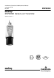
Installation, Operation & Maintenance Manual IP2040/IM, Rev. AA May 2007 1.0 MSP900SH Introduction The MSP900 ultrasonic level transmitter is designed to be mounted above a liquid and will measure the distance to the liquid surface. When programmed with details of the vessel, sump or open channel, the MSP900 will compute level, contents or flow and give a 4-20mA signal proportional to the chosen variable. Full programming details are given in the Operating Manual IP2040/OM.
Installation, Operation & Maintenance Manual IP2040/IM, Rev. AA May 2007 MSP900SH 2.
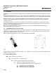
Installation, Operation & Maintenance Manual IP2040/IM, Rev. AA May 2007 3.0 MSP900SH Installation The MSP900SH may be mounted in a hazardous area provided it is supplied through or from a suitably protected power supply (such as the Mobrey Measurement MCU900 Series). Refer to the safety parameters given in section 2.2 and safety instruction leaflet IP2040/SI (-A), 71097/1131 (-U). 3.
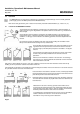
Installation, Operation & Maintenance Manual MSP900SH IP2040/IM, Rev. AA May 2007 3.1.1 General considerations • The MSP900SH transmitter complies with the European Directive for Electro Magnetic Compatibility (EMC) Class B. It is not advisable to mount the transmitter in close proximity to a source of electrical noise such as a variable speed drive or other high powered electrical device. 3.1.
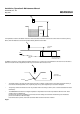
Installation, Operation & Maintenance Manual IP2040/IM, Rev. AA May 2007 MSP900SH Hmax Hmax It is important to note that the bottom reference of the transmitter should be related to the centre of the invert of the primary device, NOT the distance to the channel bottom directly below the transmitter. Transmitter bottom Flow Channel invert Primary element (eg.
Installation, Operation & Maintenance Manual MSP900SH • IP2040/IM, Rev. AA May 2007 In many installations, the use of a calibration device is mandatory. Mobrey Measurement offer the MSP-HVD for this purpose, details on request. In order to minimise measurement uncertainties when a calibration device is installed, it is recommended that the calibrated range should be kept to a realistic minimum. i.e. max flow plus 10mm.
Installation, Operation & Maintenance Manual IP2040/IM, Rev. AA May 2007 3.4 MSP900SH Additional components in the two wire loop 3.4.
Installation, Operation & Maintenance Manual IP2040/IM, Rev. AA May 2007 MSP900SH 3.6.1 Wiring When connecting the MSP900SH transmitter to an MSP90 Series control unit, different terminals are used in the control unit. If connected, disconnect the existing MSP90 type transducer. These terminals are not used with the new MSP900SH type transmitters.
Installation, Operation & Maintenance Manual IP2040/IM, Rev. AA May 2007 MSP900SH 5.0 Commissioning / Programming 5.1. Current Output This section gives a very brief overview to allow checking of the installation. For full programming details, refer to the Operating Manual IP2040/OM.
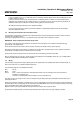
Installation, Operation & Maintenance Manual MSP900SH 6.0 Accessories 6.1 Submersion shield IP2040/IM, Rev. AA May 2007 The MSP-SUB2 is a tubular shield which slips over the black transmitter front housing. This is usually fitted in wet well installations where the liquid level could rise faster than the pumps can pump out. As the liquid covers the transmitter, an air-lock is created in the shield and the transmitter face remains free from contamination. 6.
Installation, Operation & Maintenance Manual IP2040/IM, Rev.
Installation, Operation & Maintenance Manual MSP900SH IP2040/IM, Rev. AA May 2007 Appendix 2 - Use with Mobrey Measurement MSP90 Series controllers – example Programming example when using the new MSP900SH transmitter with an old style MSP90 Series controller. A2.1 Vertical rectangular or cylindrical sump, originally displaying level in metres, 4.2m from transducer face to bottom of sump.
Installation, Operation & Maintenance Manual IP2040/IM, Rev.
Installation, Operation & Maintenance Manual IP2040/IM, Rev. AA May 2007 MSP900SH The Emerson logo is a trade mark and service mark of Emerson Electric Co. Rosemount is a registered trademark of Rosemount Inc. Mobrey is a registered trademark of Mobrey Ltd. All other marks are the property of their respective owners We reserve the right to modify or improve the designs or specifications of product and services at any time without notice.