Instruction Manual PN 51-396P/rev.
DANGER HAZARDOUS AREA INSTALLATION ESSENTIAL INSTRUCTIONS READ THIS PAGE BEFORE PROCEEDING! Rosemount Analytical designs, manufactures, and tests its products to meet many national and international standards. Because these instruments are sophisticated technical products, you must properly install, use, and maintain them to ensure they continue to operate within their normal specifications.
MODEL 396P and 396PVP TABLE OF CONTENTS MODEL 396P and 396PVP COMBINATION pH/ORP SENSOR TABLE OF CONTENTS Section 1.0 1.1 1.2 1.3 Title DESCRIPTION AND SPECIFICATIONS................................................................. Features and Applications........................................................................................ Physical Specifications............................................................................................. Ordering Information .........................
MODEL 396P and 396PVP TABLE OF CONTENTS LIST OF FIGURES Number Title Page 1-1 Cross Section Diagram of the TUpH Patented Reference Technology ............................................................................... 2 2-1 Dimensional Drawing .......................................................................................................................................................... 6 2-2 Flow-Through Tee with Adapter (PN 915240-xx)................................................
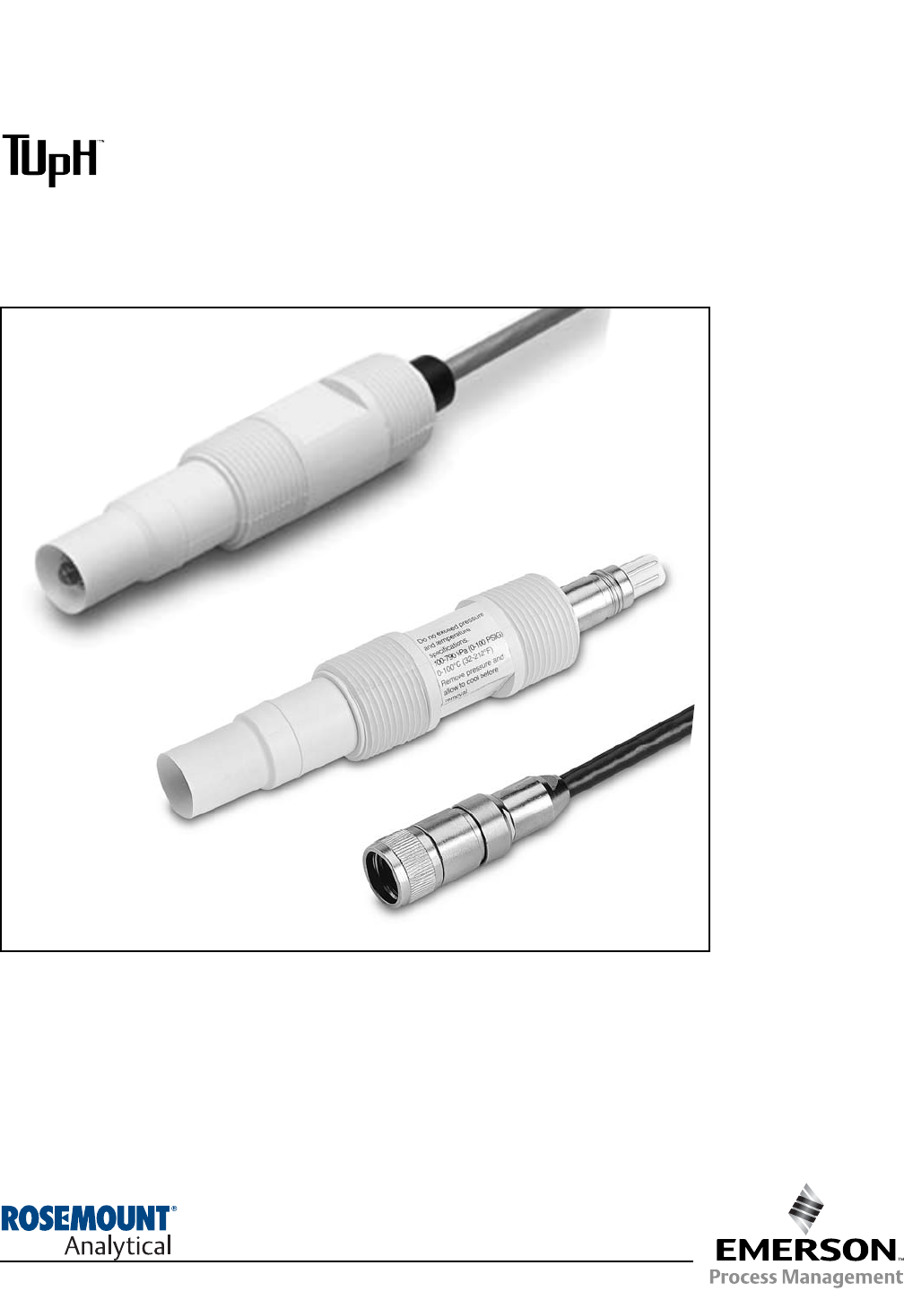
MODEL 396P and 396PVP SECTION 1.0 DESCRIPTIONS AND SPECIFICATIONS SECTION 1.0 DESCRIPTION AND SPECIFICATIONS 1.1 FEATURES AND APPLICATIONS The Rosemount Analytical Model 396P and 396PVP Sensors measure the pH or the ORP of aqueous solutions in pipelines, open tanks, or ponds. It is designed for harsh, dirty applications such as sourwater waste treatment and scrubbers, where a high performance, low maintenance, disposable sensor is required.
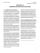
MODEL 396P and 396PVP SECTION 1.0 DESCRIPTIONS AND SPECIFICATIONS FIGURE 1-1. Cross Section Diagram of the TUpH Patented Reference Technology All TUpH sensors are designed with a large area reference junction, helical reference pathway, and an AccuGlass pH glass bulb. This patented sensor technology ensures superior performance while only requiring minimal maintenance. 1.
MODEL 396P and 396PVP SECTION 1.0 DESCRIPTIONS AND SPECIFICATIONS 1.3 ORDERING INFORMATION The Model 396P Sensor is housed in a molded reinforced polypropylene body with 1 in. MNPT threads suitable for insertion, submersion or flow through installation. The sensor includes a general purpose pH electrode or a platinum ORP electrode, a patented reference junction and a solution ground. The Model 396P comes standard with a recessed electrode; an optional slotted tip is also available.
MODEL 396P and 396PVP SECTION 1.0 DESCRIPTIONS AND SPECIFICATIONS The Model 396PVP Sensor has similar features to the Model 396P. However, the Model 396PVP is offered with the new Variopol (VP) connector and uses a mating VP cable (purchased separately). A remote preamplifier must be used with this sensor. A Variopol cable is required for all new installations. See below for cable selection.
MODEL 396P and 396PVP SECTION 2.0 INSTALLATION SECTION 2.0 INSTALLATION 2.1 UNPACKING AND INSPECTION. Inspect the outside of the carton for any damage. If damage is detected, contact the carrier immediately. Inspect the hardware. Make sure all the items in the packing list are present and in good condition. Notify the factory if any part is missing. If the sensor appears to be in satisfactory condition, proceed to Section 2.2, Mounting.
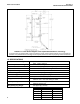
MODEL 396P and 396PVP SECTION 2.0 INSTALLATION SENSOR CABLE (OR VP CONNECTOR - NOT SHOWN) MILLIMETER INCH DWG. NO. 40396P01 FIGURE 2-1. Dimensional Drawing MILLIMETER INCH xx* 03 04 05 SENSOR CABLE (OR VP CONNECTOR - NOT SHOWN) Process Connection Threads 3/4 inch 1 inch 1-1/2 inch FIGURE 2-2. Flow-Through Tee with Adapter (PN 915240-xx*) 6 REV.
MODEL 396P and 396PVP SECTION 2.0 INSTALLATION WHEN INCH AND METRIC DIMS ARE GIVEN MILLIMETER INCH 1-1/2” X 1” Reducing Bushing 1-1/2” X 1” Reducing Bushing 1-1/2” Pipe Tee PN 2002011 ANGLE FLOW SHOWN FLOW STRAIGHT FLOW SHOWN 1-1/2” Pipe Tee PN 2002011 1-1/2” X 1” Reducing Bushing PIPE “Y” INSTALLATION SHOWN 1-1/2” PIPE “Y” FIGURE 2-3. Flow-Through and Insertion Installations DWG. NO. 40396P02 REV. A FIGURE 2-4. Model 396P with Insertion Mounting Adapter (PN 23242-02).
MODEL 396P and 396PVP SECTION 2.0 INSTALLATION WHEN INCH AND METRIC DIMS ARE GIVEN MILLIMETER INCH DWG. NO. 40396P03 REV. A Handrail Mounting Assembly PN 11275-01 DWG. NO. 40396P04 FIGURE 2-5. Submersion Installations 8 REV.
MODEL 396P and 396PVP MILLIMETER INCH SECTION 2.0 INSTALLATION SENSOR CABLE (OR VP CONNECTOR - NOT SHOWN) FIGURE 2-6. Low Flow Cell PN 23728-00 FIGURE 2-7.
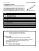
MODEL 396P and 396PVP SECTION 3.0 WIRING - MODEL 396P SECTION 3.0 WIRING — MODEL 396P-01 Figures in this section provide the guidelines for wiring the 396P-01 sensor to various Analyzer/Transmitter instruments. 2. To determine which wiring guideline to use, locate the model number of the sensor to be installed. 1. If the cable needs to be extended, use a high quality eleven conductor double shielded instrument cable available from Rosemount Analytical.
MODEL 396P and 396PVP Wiring. The Model 396P has an optional built-in preamplifier and is offered with a shielded cable. The cable should be handled carefully and kept dry and free of corrosive chemicals at all times. Extreme care should be used to prevent it from being twisted, damaged or scraped by rough, sharp edges or surfaces. Please refer to Figures 3-1 through 3-6 for wiring Model 396P-01. SECTION 3.0 WIRING - MODEL 396P DANGER DO NOT CONNECT SENSOR CABLE TO POWER LINES. SERIOUS INJURY MAY RESULT.
MODEL 396P and 396PVP SECTION 3.0 WIRING - MODEL 396P WHEN INCH AND METRIC DIMS ARE GIVEN MILLIMETER INCH DWG. NO. 40396P15 FIGURE 3-2. Wiring Details Model 396P-01-50 for use with and without Junction Box (PN 22719-02) for Model 1181. 12 REV.
MODEL 396P and 396PVP SECTION 3.0 WIRING - MODEL 396P WHEN INCH AND METRIC DIMS ARE GIVEN MILLIMETER INCH DWG. NO. 40396P13 REV. D FIGURE 3-3. Wiring Details Model 396P-01-54 for use with and without Junction Box (PN 22719-02) for Models 1054A, 1054B, 2054, 2081, and Extension Cable (9200254).
MODEL 396P and 396PVP SECTION 3.0 WIRING - MODEL 396P WHEN INCH AND METRIC DIMS ARE GIVEN MILLIMETER INCH DWG. NO. 40396P08 FIGURE 3-4. Wiring Details Model 396P-01-55 for use with Junction Box (PN 23550-00) for Models 54e, 3081, 4081, 81, and 5081. 14 REV.
MODEL 396P and 396PVP SECTION 3.0 WIRING - MODEL 396P FIGURE 3-5. Wiring Details Model 396P-01-55 for use with Models 54e, 81, 3081, 4081, and 5081 FIGURE 3-6.
MODEL 396P and 396PVP SECTION 4.0 WIRING - MODEL 396PVP SECTION 4.0 WIRING — MODELS 396P-02 AND 396PVP Figures 4-1 thru 4-22 provide the guidelines for wiring the sensor to various Analyzer/Transmitter instruments. To determine which wiring guideline to use, locate the model number of the sensor to be installed. 1. If the cable needs to be extended, use a high quality eleven conductor double shielded instrument cable available from Rosemount Analytical.
MODEL 396P and 396PVP SECTION 4.0 WIRING - MODEL 396PVP FIGURE 4-1. Wire Functions for Mating Variopol Cable used with Model 396PVP FIGURE 4-2. Connector Pins and Their Functions FIGURE 4-3. Wiring Details for Models 396PVP or 396P-02-55 with Mating Variopol Cable (PN 23645-07) for use with Model 81 FIGURE 4-4. Wiring Details for Models 396PVP or 396P-02-50 with Mating Variopol Cable (PN 23645-07) for use with Model 1181 FIGURE 4-5.
MODEL 396P and 396PVP FIGURE 4-7. Wiring Details for Models 396PVP or 396P-02-55 with Mating Variopol Cable (PN 23645-07) for use with Remote Junction Box (PN 23555-00) to Model 81 FIGURE 4-9. Wiring Details for Models 396PVP or 396P-02-55 with Mating Variopol Cable (PN 23645-07) for use with Model 54/54e 18 SECTION 4.0 WIRING - MODEL 396PVP FIGURE 4-8.
MODEL 396P and 396PVP FIGURE 4-11. Wiring Details for Models 396PVP or 396P02-54 with Mating Variopol Cable (PN 23645-06) for use with Remote Junction Box (PN 23309-04) to Model 2081 FIGURE 4-13. Wiring Details for Models 396PVP or 396P-02-54 with Mating Variopol Cable (PN 23645-07) for use with Model 1054 SECTION 4.0 WIRING - MODEL 396PVP FIGURE 4-12.
MODEL 396P and 396PVP SECTION 4.0 WIRING - MODEL 396PVP FIGURE 4-15. Wiring Details for Models 396PVP or 396P-02-55 with Mating Variopol Cable (PN 23645-07) for use with Model 1055 FIGURE 4-16. Wiring Model 396P-(02)-( )--54/55-(61) Sensor to Model 1055-01-10-22-32 Analyzer FIGURE 4-17. Wiring Details for Models 396PVP or 396P-02-55 with Mating Variopol Cable (PN 23645-07) for use with Remote Junction Box (PN 23557-00) to Model 1055 NOTE: This wiring diagram can also be used for wiring a Model 396P-01.
MODEL 396P and 396PVP SECTION 4.0 WIRING - MODEL 396PVP FIGURE 4-18. Wiring Details for Models 396PVP or 396P-02-54 with Mating Variopol Cable (PN 23645-06) for use with Models 1054A/B & 2054 FIGURE 4-19. Wiring Details for Models 396PVP or 396P-02-54 with Mating Variopol Cable (PN 23645-06) for use with Remote Junction Box (PN 23309-04) to Models 1054A/B and 2054 FIGURE 4-20.
MODEL 396P and 396PVP SECTION 4.0 WIRING - MODEL 396PVP DWG. NO. 40396P25 REV. A FIGURE 4-21. Wiring Details Model 396P-02-50 for use with Junction Box (PN 23309-03) and Remote Preamplifier, Extension Cable (PN 9200254). DWG. NO. 40396P24 FIGURE 4-22. Wiring Details Model 396P-02-54 for use with Junction Box (PN 23309-04) and Remote Preamplifier (PN 22698-03), Extension Cable (9200254). 22 REV.
MODEL 396P and 396PVP SECTION 4.0 WIRING - MODEL 396PVP FIGURE 4-23. Wiring Model 396P-01 to Model Xmt-P-HT-10 FIGURE 4-24.
MODEL 396P and 396PVP SECTION 5.0 START UP AND CALIBRATION SECTION 5.0 START UP AND CALIBRATION 5.1 MODELS 396P and 396PVP pH SENSORS 5.1.1 SENSOR PREPARATION. Shake down the sensor to remove any air bubbles that may be present at the tip of the pH glass bulb. In most cases, the pH sensor can simply be installed as shipped and readings with an accuracy of ± 0.6 pH may be obtained.
MODEL 396P and 396PVP SECTION 6.0 MAINTENANCE SECTION 6.0 MAINTENANCE The Model 396P and 396PVP Sensors require minimum maintenance. The sensor should be kept clean and free of debris and sediment at all times. The frequency of cleaning by wiping or brushing with a soft cloth or brush is determined by the nature of the solution being measured. The sensor should be removed from the process periodically and checked in buffer solutions.
MODEL 396P and 396PVP 6.3 MODEL 396P and 396PVP ORP 4.3.1 Platinum Electrode Check. The platinum electrode may be checked as follows: There are two types of standard solutions which may be used to check the ORP electrode/transmitter system. Type 1: One type of commonly used ORP standard solution is the saturated quinhydrone solution. Refer to Section 5.2. CAUTION The solution used during the following check is an acid and should be handled with care. Follow the directions of the acid manufacturer.
MODEL 396P and 396PVP SECTION 7.0 DIAGNOSTICS AND TROUBLESHOOTING SECTION 7.0 DIAGNOSTICS AND TROUBLESHOOTING 7.1 MODEL 54e/81/3081/4081/5081/Xmt DIAGNOSTICS AND TROUBLESHOOTING The Model 54 Analyzer and Models 81 and 3081 Transmitters automatically search for fault conditions that would cause an error in the measured pH value, as does the Model 1054B pH/ORP Analyzer to a lesser degree. Refer to the applicable Instruction Manual for a complete description of the analyzer’s fault conditions.
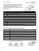
MODEL 396P and 396PVP SECTION 7.0 TROUBLESHOOTING 7.2 TROUBLESHOOTING WITHOUT ADVANCED DIAGNOSTICS. Table 7-2, below, lists common problems, causes and remedies typically encountered in process measurement. TABLE 7-2. Troubleshooting without Advanced Diagnostics Problem Probable Cause Remedy Meter reads off scale. (Display reads overrange). Defective preamplifier Replace preamplifier (for code 02 sensors). For code 01, replace sensor. T.C. element shorted Check T.C.
MODEL 396P and 396PVP SECTION 7.0 TROUBLESHOOTING TABLE 7-3. Model 396P and 396PVP pH/ORP Replacement Parts and Accessories PN DESCRIPTION 11275-01 Sensor Handrail Mounting Assembly 2002011 Flow Cell, CPVC, 1 inch FNPT QUANTITY 23242-02 Mounting Adapter, Insertion, 1¼-inch MNPT (304 S.S.
MODEL 396P and 396PVP SECTION 8.0 RETURN OF MATERIAL SECTION 8.0 RETURN OF MATERIAL 8.1 GENERAL. 8.3 NON-WARRANTY REPAIR. To expedite the repair and return of instruments, proper communication between the customer and the factory is important. Before returning a product for repair, call 1-949-757-8500 for a Return Materials Authorization (RMA) number. The following is the procedure for returning for repair instruments that are no longer under warranty: 1. Call Rosemount Analytical for authorization.
WARRANTY Seller warrants that the firmware will execute the programming instructions provided by Seller, and that the Goods manufactured or Services provided by Seller will be free from defects in materials or workmanship under normal use and care until the expiration of the applicable warranty period. Goods are warranted for twelve (12) months from the date of initial installation or eighteen (18) months from the date of shipment by Seller, whichever period expires first.
The right people, the right answers, right now. ON-LINE ORDERING NOW AVAILABLE ON OUR WEB SITE http://www.raihome.com Specifications subject to change without notice. Credit Cards for U.S. Purchases Only. Emerson Process Management Liquid Division 2400 Barranca Parkway Irvine, CA 92606 USA Tel: (949) 757-8500 Fax: (949) 474-7250 http://www.raihome.com © Rosemount Analytical Inc.