
Instruction Manual


Instruction Manual
748213-S
April 2002
6-4 Maintenance and Service Rosemount Analytical Inc. A Division of Emerson Process Management
Model 755R
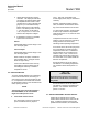
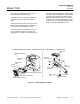
Side View
of Connector
Keeper
Connector Pin Removed
Upper Slot
Lower Slot
Connector Pin/
Leads in Place
Improvised Pin Removal Tool, Such as a Paper Clip
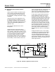
6-4 DETECTOR CHECK
To isolate the detector as the problem, it is
necessary to check the source lamp, photo-
cells, and suspension (see Figure Figure
6-1B, page 6-3). These components are con-
nected via J12 on the optical bench assembly.
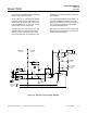
Pin/leads may be removed from connector
J12 by use of an improvised pin removal tool,
such as a paper clip (see Figure 6-2 below).
Connect J12 has slots at top and bottom. To
remove a connector pin/lead, insert the tool
into the upper or lower slot and push down on
the end to release the keeper on the pin.
When inserting a pin/lead, its keeper must
face toward the slot opening in the connector
in order to lock in. If inserted otherwise, the
pin/lead will be forced out when the two con-
nectors are joined.
Figure 6-2. Pin/Lead Removal
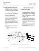
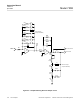
Figure 6-3. Detector Optical Bench
Hole for Source Lamp
When dual photocell is installed,
the gap between the two
photocells should be in position
indicated by this line.
O
p
tical Bench
10
J12
1
HR2
Suspension
Heater
PUR
GRN
18
BLK
BLK
WHT
WHT
RT1
Suspension
Terminals