
Instruction Manual


Instruction Manual
748213-S
April 2002
Rosemount Analytical Inc. A Division of Emerson Process Management Maintenance and Service 6-1
Model 755R
SECTION 6
MAINTENANCE AND SERVICE
The information provided in this section will
aid in isolation of a malfunction to a particular
assembly or circuit board. A few detailed
checks are included, to aide in locating the
defective assembly.
It is recommended that those familiar with cir-
cuit analysis, refer to Section 6 Circuit Analy-
sis of this manual.
WARNING
ELECTRICAL SHOCK HAZARD
Do not operate without doors and covers
secure. Servicing requires access to live
parts which can cause death or serious
injury. Refer servicing to qualified per-
sonnel.
For safety and proper performance this in-
strument must be connected to a properly
grounded three-wire source of power.
Optional alarm switching relay contacts
wired to separate power sources must be
disconnected before servicing.
WARNING
PARTS INTEGRITY
Tampering or unauthorized substitution of
components may adversely affect safety of
this product. Use only factory docu-
mented components for repair
6-1 INITIAL CHECKOUT WITH STANDARD
GASES
If instrument readings do not meet specifica-
tions, the first step in troubleshooting is to
isolate the analyzer from the sample stream
and the sample handling system.
Admit zero and span standard gases to the
analyzer. Observe readout on digital display,
and on recorder, if used.
Digital display gives correct reading with
standard gases, but not with sample gas
The sample and the sample handling system
are suspect. Check these areas.
Digital display gives correct readings with
standard gases, but the alarm or output
devices do not
Check these devices individually.
Digital display gives overrange readings
with standard gases, as well as sample
gas
The problem is likely with detector or the
electronic circuitry. Turn power OFF. Tap
detector compartment with fingers, wait 30
seconds, reapply power. If the suspension
within the detector assembly is hung up, this
may correct the problem. If not, proceed with
checks of the detector and electronic circuitry.
Digital display gives erratic readings with
standard gases, as well as sample gas
If zero and span standard gases give noisy or
drifting readings, the problem is probably in
the detector or the temperature control cir-
cuits. Proceed with checks of the detector
and electronics. In general, before concluding
that the detector is defective and must be re-
placed, verify correct operation of all circuits
that could cause erratic readings.
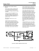
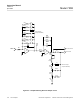
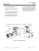
a. Control Board Checkout
The Detector Isolation Plug located on the
Control Board (Figure 3-1, page 3-3), re-
moves the detector signal, allowing the
input voltage to go to zero. The display
should register near zero or on scale, and
TP20 should read zero voltage. To test
the remainder of the measuring circuit, do
the following:
Voltage
1. Set RANGE Select to lowest range.