
Instruction Manual


Instruction Manual
748213-S
April 2002
Rosemount Analytical Inc. A Division of Emerson Process Management Circuit Analysis 5-11
Model 755R
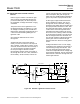
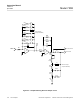
5-9 ANALOG OUTPUT CIRCUITS FOR RE-
CORDER AND ALARMS
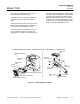
Refer to Figure 5-8, page 5-12. The analog
output circuits utilize two amplifiers, first-stage
amplifier and second-stage amplifier.
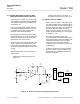
a. First Stage Amplifier
Permits selection of the desired fullscale
oxygen range for the recorder via
jumper-selectable signal amplification for
scale expansion. This amplifier permits
selecting the desired fullscale oxygen
range for the recorder by an appropriate
jumper selection of one of seven recorder
spans. The following recorder spans are
available: 1, 2.5, 5, 10, 25, 50, and 100%.
b. Second Stage Amplifier
Provides (a) a jumper-selectable output
for a potentiometric recorder and (b) an
output to drive the voltage-to-current
and/or alarm option(s), if used. This am-
plifier is an inverting configuration that
provides a signal attenuation of 2X, thus
reducing the 10-volt fullscale input signal
to obtain a 5-volt fullscale output. This
output is routed to:
1. Recorder Output Resistor Network. It
provides a jumper-selectable output
of 0 to 10 mV, 0 to 100 mV, 0 to 1 V,
or 0 to 5 VDC for a potentiometric re-
corder.
2. Current Output Receptacle J1. This
connector accepts the optional plug-in
current-output board.
3. Dual Alarm Amplifier Circuit. This cir-
cuit drives the optional 654019 Alarm
Relay Assembly.
Oxygen is strongly paramagnetic while
most other common gases are weakly
diamagnetic. The paramagnetism of oxy-
gen may be regarded as the capability of
an oxygen molecule to become a tempo-
rary magnet when placed in a magnetic
field. This is analogous to the magnetiza-
tion of a piece of soft iron. Diamagnetic
gases are analogous to non-magnetic
substances.
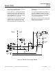
With the Model 755R, the volume mag-
netic susceptibility of the flowing gas
sample is sensed in the detector/magnet
assembly. As shown in the functional dia-
gram of Figure 5-1 (page 5-2), a dumb-
bell-shaped, nitrogen-filled, hollow glass
test body is suspended on a plati-
num/nickel alloy ribbon in a non-uniform
magnetic field.
Because of the “magnetic buoyancy” ef-
fect, the spheres of the test body are
subjected to displacement forces, result-
ing in a displacement torque that is pro-
portional to the volume magnetic
susceptibility of the gas surrounding the
test body.