
Instruction Manual


Instruction Manual
748213-S
April 2002
5-10 Circuit Analysis Rosemount Analytical Inc. A Division of Emerson Process Management
Model 755R
TP16
R37
2M
R38
100K
-
+
U10
C36
.47uF
R30
20K
R31
2K
TP11
C31
1.0uF
R36
1M
R61
1M
C38
.22uF
TP16
R49
20K
R39
11K
C40
1.0uF
ADC
71C03
8052A
REF
DISPLAY
DRIVER AND
CONTROL
+15V
5V
U18
5V
REGULATOR
To Analog Output Circuit
(Figure 6-8)
DIGITAL
DISPLAY
5-7 BUFFER AMPLIFIERS U8 AND U10 WITH
ASSOCIATED ANTICIPATION FUNCTION
Refer to Figure 5-8, page 5-12. U8 is a unity
gain amplifier that provides zeroing capability
and a buffered output for the anticipation cir-
cuit feeding U10.
U10 is an inverting buffer amplifier that incor-
porates an anticipation arrangement in its in-
put network, thus providing slightly faster
response on the readout device(s).
Potentiometer R30 provides a continuously
variable adjustment of 5 to 25 seconds for the
electronic response time (90% of fullscale)
and is factory-set for 20 seconds.
Since the anticipation network attenuates the
signal, a gain of 10 is provided by the feed-
back network associated with U10 to restore
the signal to the desired fullscale range of 0 to
10 VDC.
The output signal from U10 is routed to two
output circuits:
Digital output circuit (See Section 5-8,
page 5-10).
Analog output circuits for recorder, V/I
and alarms (See Section 5-9, page 5-11).
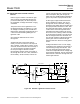
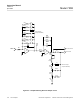
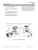
5-8 DIGITAL OUTPUT CIRCUIT
Refer to Figure 5-7 below. The output signal
from buffer amplifier U10 is routed through an
attenuator and filter network to an integrating
analog-to-digital converter. It converts the sig-
nal into an equivalent digital value in the
range of 0.00% to 99.99%. Any value above
99.99% will be preceded by an over-range bit,
for example, 1.1123.
The output of the ADC consists of bi-
nary-coded decimal characters that are input
to the liquid crystal controller and display chip
characters sequentially in time. The BCD
characters are converted into seven-line
codes to drive the bar segments of the liquid
crystal display.
A separate regulator circuit, which operates
from the +15 VDC supply, provides a regu-
lated 5 VDC for the digital functions associ-
ated with the display.
Figure 5-7. Buffer, Anticipation, and Digital Output Circuits