
Instruction Manual


Instruction Manual
748213-S
April 2002
Rosemount Analytical Inc. A Division of Emerson Process Management Circuit Analysis 5-9
Model 755R
SIG. Vx 0 -+ 10V
CONTROL
BOARD
DETECTOR
HOUSING
+15V
-15V
CR2
C2
1000
p
f
C4
.01uF
R3
110
TP6
R5
2M
C3
.47uF
R6
118K
R4
1.13K
TP7
-
+
U1
C1
3.3uF
R2
249K
R1
10
DS1
BT1
R1
1K
BT2
-
+
U1
R2
1K
R3
1K
R2
1K
CURRENT
FEEDBACK
LOOP
-
+
U2
-
+
U4
R21
49.9K
R22
49.9K
R23
150K
TP20
R20
20K
E21 E22
TP10
R7
1.77K
R8
1.77K
C7
.47uF
C8
.0022uF
R10
3.01K
R12
200K
R9
20K
R13
20K
+15V
-15V
+15V
-15V
DETECTOR
COARSE
ZERO
FRONT
PANEL
ZERO
-
+
U2
TP8
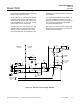
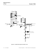
will cause the dumbbell and mirror to be posi-
tioned correctly in the test body.
As the charge on C1 increases, the cathode
of CR2 becomes more positive. When it ex-
ceeds that on the anode, CR2 ceases to con-
duct and isolates the +15 VDC and -15 VDC
power supply from the input circuit.
The front panel zero potentiometer R13 and
detector coarse zero potentiometer add or
subtract current to the input of U2 to offset
any currents that may occur because of any
imbalance in the detector and the photocells
BT1 and BT2.
The output current that U2 must provide to re-
store the dumbbell is a measure of the dis-
placing force and thus is a function of both (a)
the % oxygen concentration of the sample
and (b) the sample pressure.
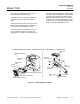
The output from the U1 and U2 loop is further
amplified by U4 to provide a 0 to 10 VDC out-
put that constitutes signal V.
Figure 5-6. Detector with First Stage Amplifier