
Instruction Manual


Instruction Manual
748213-S
April 2002
5-8 Circuit Analysis Rosemount Analytical Inc. A Division of Emerson Process Management
Model 755R
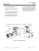
5-6 DETECTOR WITH FIRST STAGE AMPLIFIER
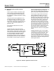
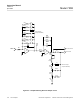
Refer to Figure 5-6, page 5-9. The detector
assembly consists of a test body suspended
on a platinum wire and located in a
non-uniform magnetic field.
The test body is constructed of two hollow
glass spheres forming a dumbbell shape.
They are filled and sealed with pure, dry nitro-
gen. Around the test body, a titanium wire is
chemically etched in order to form a feedback
loop that can create a counteracting magnetic
force to the test body displacement caused by
oxygen concentration in the test assembly
magnetic field.
Attached to the center arm of the test body
dumbbell is a diamond-shaped mirror. At-
tached to the mirror are two separate platinum
wires in tension with the supports for the test
body. The supports are isolated from ground
and are electrically connected to the feedback
loop and the electronics for that loop. The
platinum wires form a fulcrum around which
the test body pivots.
The detector operates in the following fashion.
If the sample gas contains oxygen, it collects
in the non-uniform magnetic field around the
test body. Oxygen, because of its paramag-
netic qualities, gathers along the magnetic
lines of flux and forces the dumbbell of the
test body out of the magnetic field.
A light source is focused on the test body mir-
ror. As the test body moves out of the mag-
netic field, the mirror distributes light unevenly
on two photocells (BT1 and BT2). The photo-
cells create a current proportional to light. This
current is converted to a ± voltage by U1 and
U2 located on the connector board in the de-
tector housing. This voltage is then presented
to comparator U1 on the controller board. The
output of U1 goes to U2. The output of U2
causes current to flow through the feedback
loop attached to the dumbbell.
This feedback current creates an elec-
tro-magnetic field that attracts the dumbbell
and mirror into the test assembly magnetic
field until the mirror reflects light almost uni-
formly on each photocell. A current propor-
tional to the oxygen concentration in the mag-
netic field of the test assembly has to be
flowing through the feedback loop in order to
maintain balance and provide a reading of the
oxygen content of a sample.
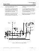
Resistances R7, R8 and the resistance of the
wire in the feedback loop determine the gain
of amplifier U2. The mirror on the dumbbell is
positioned by the amount of current in the
feedback loop. The mirror reflects light from
the source (DS1) to the photocells (BT1,
BT2). This repositioning of the mirror is a form
of mechanical feedback to the input of the
amplifier U1.
The net result is that the output of U1 could
vary from 0 to -70 mV, or 0 to -7.0 V, de-
pending on the range of the instrument. R4,
C3 and R5, C7 form damping circuits for the
input amplifier U1 and to smooth out noise
that might be introduced by the measurement
source.
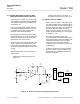
Diode CR2 is a low-leakage device. Its pur-
pose in the circuit is to ensure that the dumb-
bell and mirror are positioned correctly with
respect to the photocells on initial application
of power.
If the dumbbell was out of position on start-up,
the mirror might reflect light from the source
onto one of the photocells. If the photocell
output was positive, the current in the feed-
back loop would be in the wrong direction and
its electromagnetic field would cause the
dumbbell to be further repelled from the per-
manent magnetic field. The result would be
error, not balance.
On application of AC power, capacitor C1 has
no charge. The current will have to flow
through R2. Initially the full 30 V drop (the
difference between the +15 VDC and -15
VDC power) will appear cross R2. The cath-
ode of CR2 will be initially at -15 VDC. The
anode of CR2 will be some value more posi-
tive than -15 VDC. CR2 will conduct. The in-
put terminal of U1 will be negative and the
current through the feedback loop around U2