
Instruction Manual


Instruction Manual
748213-S
April 2002
5-4 Circuit Analysis Rosemount Analytical Inc. A Division of Emerson Process Management
Model 755R
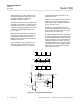
Capacitor C37 will now start to charge posi-
tively through R78. When the positive poten-
tial across C37 and at the inverting terminal of
comparator 3 exceeds the potential on the
non-inverting terminals, the transistor con-
ducts. The output is -15 V. A full 30 V drop
appears across R77.
The potential on the non-inverting terminal will
now be about -2.3 V. C37 will not discharge
through R78 until its potential exceeds that on
the non-inverting terminal. At that time, com-
parator 3 will switch polarity and start charging
C37 again. The result is that the potential
across C37 will vary almost linearly with time
and form a ramp signal of about 6 Hz.
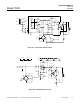
As the potential across C37 increases and
decreases linearly, it affects the potential at
the top of the bridge circuit between R82 and
R83 through R74. Because of the ramp action
charging and discharging C37, the potential
between R82 and R83 varies approximately
from -1.85 V to -1.92 VDC.
The temperature sensing device, RT1, in the
bridge circuit is a thermistor. The bridge is de-
signed to control the temperature in the case
at 135°F (57°C). When the temperature is
135°F (57°C), the resistance of the thermistor
RT1 will be at its lowest and the potential at
the junction of RT1 and R84 should be the
same as the junction of R82 and R83. Com-
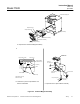
parator 4 (See Figure 5-4, page 5-6) does not
allow pulses from the OR circuit (comparators
1 and 2) to operate Q6 or Triac Q7 in the case
heater (See Figure 5-5, page 5-7).
Theoretically, at 135°F (57°C) the potential at
the junction of RTR1 and R84 is -1.85VDC.
This is equivalent to a resistance of 21.2 K. By
substituting a decade box for the thermistor
and placing 20.2 K into the bridge, the heater
should be off. With 22.7 K, the heater should
be full on.
Since the potential at the junction of R82 and
R83 can vary between 1.85V and 1.92V ac-
cording to the 6 Hz ramp, and the potential at
the junction of RT1 and R84 may vary around
or within these limits, depending on tempera-
ture, the error signal to comparator 4 may
vary from 0mV to some absolute value. The
polarity of the error signal will depend on the
deviation from the desired temperature and
the ramp value at the function of R82 and
R83.
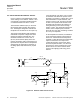
The input from the OR circuit comparator (See
Figure 5-1, page 5-2) is either -15 VDC or the
ramp effect on the bridge. When -15V, the
junction of R82 and R83 is also this value.
The error signal into comparator 4 is nega-
tively large to the inverting terminal. Com-
parator 4 output transistor does not conduct.
The base of Q6 is positive; therefore, Q6 does
not conduct and a charge builds up on ca-
pacitor C38.
The input from the OR comparators 1 and 2
form multivibrator circuit, pulses 120 times a
second. For about 100 microseconds the
junction of R82 and R83 is some value be-
tween -1.85 V and -1.92 V, depending on the
ramp generator. For this brief period of time
(one pulse), comparator 4 compares the po-
tential of junction R82, R83 with junction RT1,
R84 of the bridge circuit. If the temperature at
RT1 is low, the potential at the non-inverting
terminal of comparator 4 is more negative and
the output is -15 V.
The base of Q6 is zero, because of the volt-
age drops across R79 and R80. Therefore,
Q6 conducts. Energy, stored in C38, flows
through Q6 as current and capacitor C38 dis-
charges to zero potential. No current flows
through the primary winding of transformer
T2.
At the end of the 100 microsecond pulse, the
NPN transistor in the output of comparator 4
ceases to conduct, so the signal on the base
of Q6 is +15V. Q6 ceases to conduct. C38
starts to charge, driving electrons (current)
through the primary of T2. This induces a
pulse into the secondary of T2 and to the gate
of Triac Q7 turning it on.
At the beginning of the next 100 microsecond
pulse, comparator 4 output is again -15V, with
zero volts on the base of Q6. Q6 again con-
ducts, discharging C38. At the end of the 100
microsecond pulse, Q6 ceases to conduct.