
Instruction Manual


Instruction Manual
748213-S
April 2002
Rosemount Analytical Inc. A Division of Emerson Process Management Theory 4-5
Model 755R
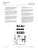
Input Amplifier U1
This amplifier receives the error signal
from the dual photocell of the detector as-
sembly and drives amplifier U2.
Amplifier U2 and Associated Zero Ad-
justment
Amplifier U2 supplies the restoring current
to the titanium wire loop of the test body
within the detector assembly. Front panel
ZERO Control R13 applies an adjustable
zero biasing signal to the input of U2 to
permit establishing a zero calibration point
on the display or recorder. With zero
standard gas flowing through the ana-
lyzer, the ZERO control is adjusted for the
appropriate reading.
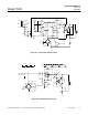
Amplifier U4 and Associated Span
Adjustment
Amplifier U4 and associated feed back
resistors provide a signal amplification of
X4. Front panel SPAN adjustment R20
modifies the value of the input resistance
and hence the signal amplification factor.
Adjustment range is approximately ±30%.
Amplifier U8
This unity gain amplifier provides zeroing
capability and a buffered output for the
anticipation circuit feeding U10.
Amplifier U10
U10 is an inverting buffer amplifier that in-
corporates an anticipation arrangement in
its input network, thus providing slightly
faster response on the readout device(s).
Potentiometer R30 provides a continu-
ously variable adjustment of 5 to 25 sec-
onds for the electronic anticipation time
and is factory-set for 20 seconds.
Since the anticipation network attenuates
the signal, a gain of 10 is provided in U10
to restore the signal to the desired full-
scale range of 0 to 10 VDC.
The output signal from U10 is routed to
two output circuits: a digital and an ana-
log.
In the Digital Output Circuit, the signal
from U10 passes to an integrating ana-
log-to-digital converter. The resulting
digital signal drives the liquid crystal dis-
play.
In the Analog Output Circuit, the output
from U10 is provided as an input to the
recorder output amplifier. This circuitry
provides scale expansion, and amplifica-
tion preparatory to use for potentiometric
recorder, voltage-to-current conversion for
current recorder, and/or alarm functions.
Potentiometric output is strap-selectable
for 0 to 10 mV, 0 to 100 mV, 0 to 1 V, or 0
to 5VDC. Potentiometer R88 permits ad-
justment of recorder span on 0 to 1 V, 100
mV and 10 mV outputs.
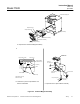
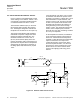
c. Power Supply Board Assembly
The Power Supply Board assembly con-
tains power supply and temperature con-
trol circuitry. The assembly is mounted
within the analyzer case.
As shown in DWG 617186, the various
circuits operate on main power trans-
former T1. During instrument assembly,
the two primary windings of T1 are fac-
tory-connected for operation on either 115
VAC or 230 VAC, as noted on the name
rating plate.
The same circuit board contains the fol-
lowing:
Source Lamp Power Supply Section
This circuit provides a regulated output of
2.20 VDC to operate incandescent source
lamp DS1 within the optical bench as-
sembly. One secondary of main power
transformer T1 drives a fullwave rectifier
consisting of CR7 and CR8. The output of
DS1 is held constant by a voltage regu-
lator circuit utilizing U7, Q4 and Q5.