
Instruction Manual


Instruction Manual
748213-S
April 2002
Rosemount Analytical Inc. A Division of Emerson Process Management Theory 4-1
Model 755R
SECTION 4
THEORY
4-1 PRINCIPLES OF OPERATION
Oxygen is strongly paramagnetic while most
other common gases are weakly diamagnetic.
The paramagnetism of oxygen may be re-
garded as the capability of an oxygen mole-
cule to become a temporary magnet when
placed in a magnetic field. This is analogous
to the magnetization of a piece of soft iron.
Diamagnetic gases are analogous to
non-magnetic substances.
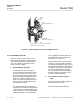
With the Model 755R, the volume magnetic
susceptibility of the flowing gas sample is
sensed in the detector/magnet assembly. As
shown in the functional diagram of Figure 5-1,
a dumbbell-shaped, nitrogen-filled, hollow
glass test body is suspended on a plati-
num/nickel alloy ribbon in a non-uniform mag-
netic field.
Because of the “magnetic buoyancy” effect,
the spheres of the test body are subjected to
displacement forces, resulting in a displace-
ment torque that is proportional to the volume
magnetic susceptibility of the gas surrounding
the test body.
Measurement is accomplished by a
null-balance system, where the displacement
torque is opposed by an equal, but opposite,
restorative torque. The restorative torque is
due to electromagnetic forces on the spheres,
resulting from a feedback current routed
through a titanium wire conductor wound
lengthwise around the dumbbell.
In effect, each sphere is wound with a
one-turn circular loop. The current required to
restore the test body to null position is directly
proportional to the original displacement
torque, and is a linear function of the volume
magnetic susceptibility of the sample gas.
The restoring current is automatically main-
tained at the correct level by an electro-optical
feedback system. A beam of light from the
source lamp is reflected off the square mirror
attached to the test body, and onto the dual
photocell.
The output current from the dual photocell is
equal to the difference between the signals
developed by the two halves of the photocell.
This difference, which constitutes the error
signal, is applied to the input of an amplifier
circuit that provides the restoring current.
When the test body is in null position, both
halves of the photocell are equally illuminated,
the error signal is zero, and the amplifier is
unequal. This condition results in application
of an error signal to the input of the amplifier
circuit. The resultant amplifier output signal is
routed through the current loop, thus creating
the electromagnetic forces required to restore
the test body to null position.
Additionally, the output from the amplifier is
conditioned as required to drive the digital
display, and recorder if used. The electronic
circuitry involved is described briefly in Sec-
tion 4-3 (page 4-4) and in greater detail in
Section 5.