
Instruction Manual


Instruction Manual
748213-S
April 2002
Rosemount Analytical Inc. A Division of Emerson Process Management Operation 3-7
Model 755R
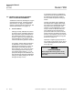
0.0 0.1 0.2 0.3 0.4 0.5 0.6 0.7 0.8 0.9 1.0
0 1 2 3 4 5 6 7 8 9 10
Percentage Oxygen Readout
Setpoint Dial Reading
0.0 0.1 0.2 0.3 0.4 0.5 0.6 0.7 0.8 0.9 1.0
0 1 2 3 4 5 6 7 8 9 10
Percentage Oxygen Readout
Setpoint Dial Reading
0 1 2 3 4 5 6 7 8 9 10
0 1 2 3 4 5 6 7 8 9 10
Percentage Oxygen Readout
Setpoint Dial Reading
0 2.5 5 7.5 10 12.5 15 17.5 20 22.5 25
0 1 2 3 4 5 6 7 8 9 10
Percentage Oxygen Readout
Setpoint Dial Reading
0 5 10 15 20 25 30 35 40 45 50
0 1 2 3 4 5 6 7 8 9 10
Percentage Oxygen Readout
Setpoint Dial Reading
0 10 20 30 40 50 60 70 80 90 100
0 1 2 3 4 5 6 7 8 9 10
Percentage Oxygen Readout
Setpoint Dial Reading
0.0 0.5 1.0 1.5 2.0 2.5 3.0 3.5 4.0 4.5 5.0
0 1 2 3 4 5 6 7 8 9 10
Percentage Oxygen Readout
Setpoint Dial Reading
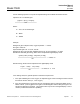
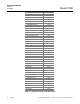
0 to 1
0 to 2.5
0 to 5
0 to 10
0 to 25
0 to 1
0 to 50
0 to 100
RANGE
%
OXYGEN
PERCENTAGE OXYGEN READOUT
versus
ALARM SETPOINT DIAL READING
3-6 SELECTION OF SETPOINTS AND DEAD-
BAND ON ALARM OPTION
The ALARM 1 and ALARM 2 setpoint adjust-
ments (see Figure 3-1, page 3-3) are adjust-
able for any desired value from 1% to 100% of
the fullscale analyzer span. The adjustment
screws are graduated from 0 to 10.
Required dial settings for both setpoint ad-
justments may be determined from either Fig-
ure 3-2 or the appropriate equation that
follows:
• Zero-based operating range
•
Required control setting =
Figure 3-2 example:
Operating range, 0 to 5% oxygen
Desired ALARM 1 setpoint = 4% oxygen
Turn potentiometer R64 to 8
Desired ALARM 2 setpoint = 3% oxygen
Turn potentiometer R68 to 6
The desired deadband may be selected via
the appropriate trimming potentiometer, R73,
for ALARM 1 deadband adjustment and R78
for ALARM 2 deadband adjustment. For any
setpoint, deadband is adjustable from 1% of
fullscale (counterclockwise limit) to 20% of
fullscale (clockwise limit). Deadband is es-
sentially symmetrical with respect to setpoint.
3-7 CURRENT OUTPUT BOARD (OPTION)
The Current Output is set at the factor for 4 to
20 mA. If a 0 to 20 mA output is required, re-
adjust both the zero and span potentiometers
(R1 and R2) on the Current Output Board.
Figure 3-2. Dial Settings for Alarm Setpoint
Adjustments
(desired alarm setpoint)(10)
fullscale span