
Instruction Manual


Instruction Manual
748213-S
April 2002
Rosemount Analytical Inc. A Division of Emerson Process Management Operation 3-1
Model 755R
SECTION 3
OPERATION
3-1 OVERVIEW
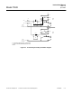
Preparatory to operation, a familiarization
with Figure 3-1 (page 3-3) is recom-
mended. This figure gives locations and
summarized descriptions of operating ad-
justments of the Model 755R Oxygen Ana-
lyzer.
3-2 OPERATING RANGE SELECTION
The Model 755R is designed to operate on
a single, field-selectable range. A new
range may be selected any time the ana-
lyzer application changes or any time cali-
bration may require a range change.
To select the operating range, reposition
the jumper shown in Figure 3-1 (page 3-3)
to the desired location. Each position is la-
beled as to its fullscale range. Only the
analog output (voltage and optional current)
is affected by range selection. The digital
display always reads 100% oxygen.
3-3 STARTUP PROCEDURE
Inject a suitable on-scale gas (not actual
sample) through the analyzer. Turn power
ON. If digital display gives overrange indi-
cation, the probable cause is the suspen-
sion in the detector is hung up. To correct
this condition, turn power OFF, tap detector
compartment with fingers, wait 30 seconds,
turn power ON.
When on-scale reading is obtained, allow
analyzer to warm-up for a minimum of one
hour with gas flowing. This warm-up is
necessary because a reliable calibration is
obtainable only after the analyzer reaches
temperature stability. Moreover, the resul-
tant elevated temperature will ensure
against condensation within, and possible
damage to the detector assembly. After
warm-up, the digital display or recorder
should give stable, drift-free readout. If so,
proceed to Section 3-4 below. Otherwise,
refer to Section 6, Maintenance and Serv-
ice.
3-4 CALIBRATION
Calibration consists of establishing a zero
calibration point and a span calibration
point (see Table 3-1, page 3-4). Zero and
span calibration should be performed on
the range that will be used during sample
analysis. In some applications, however, it
may be desirable to perform span calibra-
tion on a range of higher sensitivity (i.e.,
more narrow span) and then move the
jumper to the desired operating range. For
example, if the operating range is to be 0 to
50% oxygen, span calibration may be per-
formed on the 0 to 25% range to permit use
of air as the span standard gas.
a. Calibration with Zero and Span
Standard Gases
NOTE:
The same flow rate must be main-
tained for zero, span, and sample to
avoid measure error. The exhaust is
vented to the atmosphere to avoid
back pressure. The following pro-
cedure is based on the standards in
Table 3-2 (page 3-6). Performance
specifications are based on recorder
output.
Set Zero Calibration Point
Inject nitrogen zero standard gas
through analyzer at suitable flow rate,
preferably 250 cc/min. Allow gas to
purge analyzer for a minimum of three
minutes.
Adjust ZERO control so that the read-
ing on the digital display or recorder is
zero