
Instruction Manual


Instruction Manual
748213-S
April 2002
2-10 Installation Rosemount Analytical Inc. A Division of Emerson Process Management
Model 755R
When input signal moves upscale through this point, the
coil of ALARM 1 relay (K1) is energized, providing
continuity between the common and normally-closed
contacts of the relay.
ALARM 1 Setpoint
When input signal moves downscale through this point, the
coil of ALARM 1 relay (K1) is de-energized, providing
continuity between the common and normally-open
contacts of the relay.
ALARM 2 Setpoint
When input signal moves upscale through this point, the
coil of ALARM 2 relay (K2) is de-energized, providing
continuity between the common and normally-open
contacts of the relay.
When input signal moves upscale through this point, the
coil of ALARM 2 relay (K2) is energized, providing
continuity between the common and normally-closed
contacts of the relay.
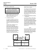
A. Typical ALARM 1 Setting
DEADBAND SET FOR
20% OF FULLSCALE
DEADBAND SET FOR
10% OF FULLSCALE
B. Typical ALARM 2 Setting
INPUT SIGNAL
Percent of Fullscale
INPUT SIGNAL
Percent of Fullscale
40
30
20
55
50
45
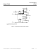
Carefully rotate R63 counter-
clockwise the minimum amount
required to obtain energization of
ALARM 1 Relay K1 (See Figure
2-6 below and Figure 3-1, page 3-
3). Energization may be verified
by connecting an ohmmeter to
relay terminals on 654019 Alarm
Relay Assembly.
c. To verify correct adjustment of
R63, adjust front panel SPAN
Control so that the display or re-
corder reads 99% of fullscale.
Relay K1 should now be
DE-ENERGIZED.
5. Adjust ALARM 2 control function as
follows:
a. With ALARM 2 Setpoint Adjust-
ment at 100% (i.e., Position 10 on
the dial), adjust front panel SPAN
Control so that
b. the display or recorder reads ex-
actly fullscale.
c. Set ALARM 2 Calibrate Adjust-
ment (R67) to its clockwise limit.
Carefully rotate R67 counter-
clockwise the minimum amount
required to obtain energization of
ALARM 2 Relay K2 (See Figure
2-5, page 2-8).
d. To verify correct adjustment of
R67, adjust front panel SPAN
Control so that the display or re-
corder reads 99% of fullscale.
Relay K2 should now be
DE-ENERGIZED.
The ALARM 1 and ALARM 2 Setpoint
Adjustments are now properly calibrated
and may be used to select the desired
alarm setpoints, as described in Section
3-6 (page 3-7).
Figure 2-6. Typical Alarm Settings