
Instruction Manual


Instruction Manual
748213-S
April 2002
Rosemount Analytical Inc. A Division of Emerson Process Management Installation 2-7
Model 755R
c. Potentiometric Output
1. Insert RECORDER OUTPUT Selector
Plug (See Figure 3-1) in position ap-
propriate to the desired output: 10
mV, 100 mV, 1V or 5V.
2. Connect leads of shielded recorder
cable to “REC OUT +” and “-” termi-
nals on the I/O board.
3. Connect the output cable to the appro-
priate terminals of the recorder or
other potentiometric device:
a. For device with span of 0 to 10
mV, 0 to 100 mV, 0 to 1V, or 0 to
5V, connect cable directly to input
terminals of the device, ensuring
correct polarity and range selec-
tion.
b. For a device with intermediate
span (i.e., between the specified
values), connect the cable to the
device via a suitable external
voltage divider (See Figure 2-3,
page 2-6).
d. Isolated Current Output (Optional)
1. Verify that the optional current output
board appropriate to desired output is
properly in place in its connector. See
Figure 3-1, page 3-3. If originally or-
dered with the analyzer, the board is
factory installed.
2. On I/O board, connect leads of
shielded recorder cable to “CUR-
RENT OUT+” and “-” terminals.
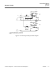
3. Connect free end of output cable to
input terminals of recorder or other
current-actuated device, making sure
that polarity is correct. If two or more
current-actuated devices are to be
used, they must be connected in se-
ries (See Figure 2-4 below). Do not
exceed the maximum load resistance
of 1000 ohms.
Current and voltage outputs may be util-
ized simultaneously if desired.
Figure 2-4. Model 755R Connected to Drive Several Current-Actuated Output Devices
N
o
t
e:
T
o
t
a
l
ser
i
es res
i
s
t
ance o
f
a
ll
d
ev
i
ces
i
s no
t
t
o excee
d
1000
o
h
ms.
755R
Analyzer
R
ecor
d
er
C
on
t
ro
ll
er
R
emo
t
e
Indicator
+
-
+
-
+
-
+
-
mA