
Instruction Manual


Instruction Manual
748213-S
April 2002
Rosemount Analytical Inc. A Division of Emerson Process Management Installation 2-5
Model 755R
2-4 LEAK TEST
WARNING
TOXIC OR CORROSIVE HAZARD
The sample containment system must be
carefully leak checked upon installation
and before initial start-up, during routine
maintenance and any time the integrity of
the sample containment system is broken,
to ensure the system is in leak proof con-
dition.
Internal leaks resulting from failure to ob-
serve these precautions could result in
personal injury or property damage.
For proper operation and safety, system leak-
age must be corrected, particularly before in-
troduction of toxic or corrosive samples and/or
application of electrical power.
To check system for leaks, liberally cover all
fittings, seals, and other possible sources of
leakage with suitable leak test liquid such as
SNOOP (P/N 837801). Check for leak indica-
tive bubbling or foaming. Leaks that are inac-
cessible to SNOOP application could evade
detection by this method.
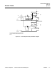
Figure 2-2. Model 755R Rear Panel
L1/HOT
L2/NEUT
GND
+ - G + -
CUR VOLT
OUTPUT OUTPUT
A B I C D E
H G H
(Rear terminal cover removed for clarity)
A. Sample outlet. 1/4” O.D. tube fitting.
B. Sample Inlet. 1/4” O.D. tube fitting.
C. 5/8” diameter hole for optional Dual Alarm Cable. Cable supplied by customer, minimum 24 AWG.
D. 5/8” diameter hole fitted with liquid-tight gland for Recorder Output Cable. Cable supplied by customer,
conductor, minimum 24 AWG.
E. 13/16” diameter hole for Power Cable. Cable supplied by customer, 3 conductor, minimum 18 AWG.
F. TB1: Customer hook-up for Power.
G. TB2: Customer hook-up for Recorder Output.
H. Optional Dual Alarm connections.
I. Connections for Optional Remote Range Change.