Quick Start Guide 00825-0100-4007, Rev CB February 2015 Rosemount 3051 Pressure Transmitter and Rosemount 3051CF Series Flowmeters with 4-20 mA HART® Revision 5 and 7 protocol Note Before installing the transmitter, confirm the correct Device Driver is loaded on the host systems. See page 3 for System Readiness.
Quick Start Guide February 2015 NOTICE This guide provides basic guidelines for Rosemount 3051 Transmitters. It does not provide instructions for configuration, diagnostics, maintenance, service, troubleshooting, Explosion-proof, Flameproof, or intrinsically safe (I.S.) installations. Refer to the Rosemount 3051 HART 7 Reference Manual (document number 00809-0100-4007) for more instruction. This manual is also available electronically on www.rosemount.com.
Quick Start Guide February 2015 System readiness Confirm HART Revision capability If using HART based control or asset management systems, please confirm the HART capability of those systems prior to transmitter installation. Not all systems are capable of communicating with HART Revision 7 protocol. This transmitter can be configured for either HART Revision 5 or 7. For instructions on how to change the HART revision of your transmitter, see page 13.
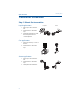
February 2015 Quick Start Guide Transmitter installation Step 1: Mount the transmitter Liquid applications Coplanar 1. Place taps to the side of the line. 2. Mount beside or below the taps. 3. Mount the transmitter so that the drain/vent valves are oriented upward. Flow Gas applications 1. Place taps in the top or side of the line. 2. Mount beside or above the taps. Flow Steam applications 1. Place taps to the side of the line. 2. Mount beside or below the taps. 3. Fill impulse lines with water.
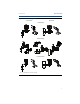
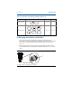
Quick Start Guide February 2015 Figure 1. Panel and Pipe Mounting Panel mount(1) Pipe mount Coplanar flange Traditional flange Rosemount 3051T 1. 1.5/16 ⫻ 11/2 Panel Bolts are customer supplied.
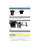
February 2015 Quick Start Guide Bolting considerations If the transmitter installation requires assembly of the process flanges, manifolds, or flange adapters, follow the assembly guidelines to ensure a tight seal for optimal performance characteristics of the transmitters. Use only bolts supplied with the transmitter or sold by Emerson as spare parts. Figure 2 on page 6 illustrates common transmitter assemblies with the bolt length required for proper transmitter assembly. Figure 2.
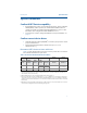
Quick Start Guide February 2015 Table 2. Torque values for the flange and flange adapter bolts Bolt material Head markings B7M Carbon Steel (CS) 316 B8M 316 R STM 316 Initial torque Final torque 300 in.-lbs. 650 in.-lbs. 150 in.-lbs. 300 in.-lbs. 316 Stainless Steel (SST) SW 316 In-line gage transmitter orientation The low side pressure port (atmospheric reference) on the in-line gage transmitter is located in the neck of the transmitter, behind the housing.
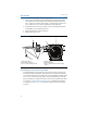
February 2015 Quick Start Guide Step 2: Consider housing rotation To improve field access to wiring or to better view the optional LCD display: 1. Loosen the housing rotation set screw using a 5/64-in. hex wrench. 2. Turn the housing left or right maximum up to 180° from its original position(1). Please note that over rotating can damage the transmitter. 3. Re-tighten the housing rotation set screw to no more than 7 in-lbs when desired location is reached. Figure 4. Transmitter Housing Set Screw A A.
Quick Start Guide February 2015 Figure 5. Transmitter Electronics Board Without LCD display With LCD or LOI display A B A. Alarm B. Security Step 4: Connect the wiring and power up Figure 6. Transmitter Wiring Diagrams (4–20 mA) A B C A. 24 Vdc supply B. RL ≥ 250 C. Current Meter (Optional) Shielded twisted pair cable should be used for best results. Use 24 AWG or larger wire that does not exceed 5,000 feet (1500 meters) in length. If applicable, install wiring with a drip loop.
February 2015 Quick Start Guide 3. Ground housing to fulfill local grounding regulations. 4. Ensure proper grounding. It is important that the instrument cable shield: a. Be trimmed close and insulated from touching the transmitter housing b. Be connected to the next shield if cable is routed through a junction box c. Be connected to a good earth ground at the power supply end 5. If transient protection is needed, refer to section “Grounding for Transient Terminal Block” for grounding instructions. 6.
Quick Start Guide February 2015 Step 5: Verify configuration Verify the configuration using any HART capable configuration tool or Local Operator Interface (LOI) - option code M4. Configuration instructions for a Field Communicator and LOI are included in this step. See Rosemount 3051 reference manual (00809-0100-4007) for configuration instructions using AMS® Device Manager.
February 2015 Quick Start Guide Table 3.
Quick Start Guide February 2015 Note See Figure 10 on page 15 to confirm External Button Functionality. Table 4. LOI Button Operation Button Left No SCROLL Right Yes ENTER Figure 9. LOI Menu Assign PV HART Revision Switch HART revision mode If the HART configuration tool is not capable of communicating with HART Revision 7, the 3051 will load a generic menu with limited capability. The following procedures will switch the HART revision mode from the generic menu: 1.
February 2015 Quick Start Guide Step 6: Trim the transmitter Devices are calibrated by the factory. Once installed, it is recommended to perform a zero trim on gage and differential pressure transmitters to eliminate error due to mounting position or static pressure effects. A zero trim can be performed using either a Field Communicator or configuration buttons. For instructions using AMS, please see the Rosemount 3051 HART 7 Product Manual (00809-0100-4007).
Quick Start Guide February 2015 Trimming with configuration buttons A zero trim is to be performed using one of the three possible sets of external configuration buttons located under the top tag. To access the configuration buttons, loosen the screw and slide the tag on the top of the transmitter. Confirm the functionality using Figure 10. Figure 10. External Configuration Buttons D A B A. LOI B. Analog Zero and Span C C. Digital Zero D.
Quick Start Guide February 2015 Safety instrumented systems installation For Safety Certified installations, refer to product manual (00809-0100-4007) for installation procedure and system requirements.
February 2015 Quick Start Guide Product Certifications European Directive Information A copy of the EC Declaration of Conformity can be found at the end of the Quick Start Guide. The most recent revision of the EC Declaration of Conformity can be found at www.rosemount.com.
February 2015 Quick Start Guide Europe E8 ATEX Flameproof and Dust Certificate: KEMA00ATEX2013X; Baseefa11ATEX0275X Standards: EN60079-0:2012, EN60079-1:2007, EN60079-26:2007, EN60079-31:2009 Markings: II 1/2 G Ex d IIC T6/T5 Ga/Gb, T6(-50 °C ≤ Ta ≤ +65 °C), T5(-50 °C ≤ Ta ≤ +80 °C); II 1 D Ex ta IIIC T95 °C T500 105 °C Da (-20 °C ≤ Ta ≤ +85 °C) Table 6. Process Temperature Temperature class Process temperature T6 -50 °C to +65 °C T5 -50 °C to +80 °C Special Conditions for Safe Use (X): 1.
Quick Start Guide February 2015 N1 ATEX Type n and Dust Certificate: BAS00ATEX3105X; Baseefa11ATEX0275X Standards: EN60079-0:2012, EN60079-15:2010, EN60079-31:2009 Markings: II 3 G Ex nA IIC T5 Gc (–40 °C ≤ Ta ≤ +70 °C); II 1 D Ex ta IIIC T95 °C T500 105 °C Da (-20 °C ≤ Ta ≤ +85 °C) Special Conditions for Safe Use (X): 1. This apparatus is not capable of withstanding the 500 V insulation test that is required by EN60079-15. This must be taken into account when installing the apparatus. 2.
February 2015 Quick Start Guide Special Conditions for Safe Use (X): 1. If the apparatus is fitted with optional 90 V transient suppressor, it is not capable of withstanding the 500 V insulation test required by IEC60079-11. This must be taken into account when installing the apparatus. 2. The enclosure may be made of aluminum alloy and given a protective polyurethane paint finish; however, care should be taken to protect it from impact or abrasion if located in Zone 0.
Quick Start Guide February 2015 2. In case of repair, contact the manufacturer for information on the dimensions of the flameproof joints. 3. The capacitance of the wrap around label, being 1.6 nF, exceeds the limit in Table 9 of ABNT NBR IEC 60079-0. The user shall determine suitability for the specific application. I2 INMETRO Intrinsic Safety Certificate: UL-BR 13.
February 2015 Quick Start Guide Japan E4 Japan Flameproof Certificate: TC20577, TC20578, TC20583, TC20584 Markings: Ex d IIC T5 Technical Regulations Customs Union (EAC) EM EAC Flameproof Certificate: RU C-US.Gb05.B.00400 Markings: Ga/Gb Ex d IIC T5/T6 X, T5(-60 °C ≤ Ta ≤ +80 °C), T6(-60 °C ≤ Ta ≤ +65 °C) Special Condition for Safe Use (X): See certificate for special conditions. IM EAC Intrinsically Safe Certificate: RU C-US.Gb05.B.
Quick Start Guide February 2015 Table 13. Thread Adapter Thread Sizes Male thread Identification mark M20 ⫻ 1.5 M20 1/2 - 14 NPT 1/2 NPT G1/2A G1/2 Female thread Identification mark M20 ⫻ 1.5 - 6H M20 1/2 - 14 NPT 1/2 - 14 NPT PG 13.5 PG 13.5 Special Conditions for Safe Use (X): 1. When the thread adapter is used with an enclosure in type of protection increased safety “e” the entry thread shall be suitably sealed in order to maintain the ingress protection rating (IP) of the enclosure. 2.
Quick Start Guide Figure 11.
February 2015 Quick Start Guide 25
Quick Start Guide 26 February 2015
February 2015 Quick Start Guide 27
00825-0100-4007 Quick Start Guide 00825-0100-4007, Rev CB February 2015 Rosemount World Headquarters Emerson Process Management 6021 Innovation Blvd Shakopee, MN 55379, USA +1 800 999 9307 or +1 952 906 8888 +1 952 949 7001 RFQ.RMD-RCC@EmersonProcess.com North America Regional Office Emerson Process Management 8200 Market Blvd. Chanhassen, MN 55317, USA +1 800 999 9307 or +1 952 906 8888 +1 952 949 7001 RMT-NA.RCCRFQ@Emerson.