
Install Instructions

2
EFFECTIVE OIL PRESSURE
Effective net oil pressure is the difference between the oil pump
outlet pressure and the compressor crankcase pressure.
EXAMPLE:
Oil Pump Outlet Pressure 40 PSIG 20 PSIG
Crankcase Pressure 10 PSIG 8’’ vacuum
Net Effective Oil Pressure 30 PSIG 24 PSIG
The FD113 measures the differential pressure between the oil
pump outlet pressure and the compressor crankcase pressure.
The FD113–ZU/ZUK is factory preset to—
Pressure Energize Timer: 10 PSID on falling pressure
De–Energize Timer: 15 PSID on rising pressure
Time–Lockout after 120 seconds of energized time
(This is Copeland factory specifications)
Manufacturer’s Setting Specifications (Typical)
Low Event PSID
Manufacturer Time Delay (seconds)
➀
(Energize timer on falling PSID)
Copeland 120 9 – 10*
Bitzer 90 9 – 10*
Carrier 45 6.5**
* Standard factory setting – 9/10 PSID Low Event. No adjustment required.
** Requires adjustment approximately 1/2 turn to left per “Checking and
Ajusting Pressure” instructions.
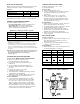
➀ Standard factory setting 120 seconds (Copeland). Adjust as required to
other manufacturer’s specifications. See figure 1 “Timer Adjustment
Button” – Verify timing utilizing either “Checking and Adjusting Timer”
procedure or “Control Checkout/Timer Checkout” procedure and readjust
as required.
NOTE:After pressure and time settings have been made and verified, a
piece of tape should be placed over the pressure setting disc slot
and timer adjustment button to prevent tampering.
(Reference figure 1)
CONTROL CALIBRATION/ADJUSTMENT
Pressure Check—BENCH TEST NO VOLTAGE APPLIED
1) Attach “Oil” connection to pressure source
(100 PSIG Max) with a low pressure gauge.
2) Leave “Low” connection at atmospheric pressure
(unattached).
3) Connect Continuity Tester between terminals 11
and 14 (safe light connection). No continuity should
be shown.
4) Pressurize oil connection to 100 PSIG.
Continuity light should energize.
5) Slowly depressurize. Continuity light should de-energize
at approximately 10 PSIG (factory).
6) Slowly re-pressurize. Continuity light should re-energize
approximately 5 PSI above de-energize pressure.
Pressure Adjustment—
1) To change pressure adjustment from factory setting,
remove control cover. Rotate notched pressure setting
disc in the control – right to increase, left to decrease
settings (see figure 1). Repeat steps 4-6 to determine
settings. Adjust/Repeat as necessary to obtain desired
timer start (minimum oil pressure setting). Note: Control
should not be set to below minimum effective oil pressure
recommended by the compressor manufacturer.
CHECKING AND ADJUSTING PRESSURE
The timer is factory preset to 120 seconds
(Copeland Specification).
Timer Checkout
1) Remove Jumper between 11 & 22.
2) Connect a continuity light across terminals 21 and 24.
No continuity should be shown (if it does, press
reset button).
3) With no pressure to the “Oil” or “Low” bellows
connections, apply 24 to 240 Volt AC/DC across
terminals 11 and “N”. The timer should trip out and
continuity should start between terminals 21 and 24
after approximately 120 seconds.
Timer Adjustment
1) Remove power from terminals 11 and “N”. Push reset
button, adjust timer button to time desired.
2) Re–energize terminals 11/“N”, observe time to trip–out
(continuity between terminals 21 and 24).
3) Repeat steps 1 and 2 until desired trip–out time is
obtained. NOTE: Control should not be set below the
minimum time specified by the manufacturer.
4) Remove power and continuity light and reinstall 11/22
Jumper, if required.
CHECKING AND ADJUSTING TIMER
Penn Ranco Robertshaw To ALCO Terminal
LLL 21
MMM 22
(Alarm when present) AS 24
V/V1 A or B
120 120 120 N
240 240 240
22T211
None None None 14 “Normal” light
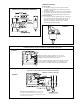
Pressure Connections
1) With the compressor depressurized (0 PSIG), connect
the bottom power element marked “Oil” to the oil
pump outlet connection.
2) Connect the top power element marked “Low” to the
compressor crankcase connection.
Electrical Wiring
1) When replacing a Ranco, Penn, or Robertshaw control,
use the following wiring cross reference.
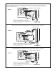
FD113 INSTALLATION
The wiring of the FD113 is illustrated in figures 4 & 5.
FIGURE 1—FD113 WITH COVER OFF