
User Guide


1. Pump down the system and the STAS shell completely.
2. Remove the cover bolts, cover, and examine the cover
gasket. If the gasket surface is damaged as indicated by
material adhering to the end of the shell the old gasket
must be discarded.
3. Withdraw the internal assembly by pulling on handle.
4. Disassemble internal assembly by unscrewing handle
while holding inlet retainer.
5. Removecontaminatedlter-drierblockorsuctionlter.
For multiple block or core units remove coupling.
6. Clean all internal parts thoroughly, giving particular care
and attention to the outlet screen.
NOTE: The ring seal is secured to outlet retainer and should
not be replaced unless it has been severely contaminated as
a result of a severe burnout.
7. Removeblockorlterfromitspackagingandreassemble
as rapidly as possible to minimize moisture contamina-
tion.
8. Install the new core in the outlet retainer taking care
to place the end of the block with the tapered inside
diameter against the outlet retainer. With multiple block
or core units place coupling between each block or core.
Positiontheinletretaineroverthenalblockorcore,and
screwthehandlermlyinplace.Carefullyinserttheas-
sembled unit into the shell assembly.
9. Lightlycoattheexistingcovergasketintheangecover
with refrigeration grade oil if determined in step 2 to be
suitable for reuse, or lightly coat a new gasket on both
surfacesandcarefullyplaceinthegrooveoftheange
cover.
10. Push the cover against the shell assembly taking care to
locate the compression spring against the inlet retainer
without hanging-up on the handle. Install a cover bolt in
the shell. Using the slotted hole with the installed bolt,
install the cover placing a cover bolt in the diagonally op-
posite bolt hole to hold the cover snugly against the shell
edge.
11. Install the remaining cover bolts snugly.
12. Torque all cover bolts evenly in a criss-cross pattern to
a torque of 30 ft. lbs. Maximum. [25 ft. lbs. maximum
for the S-V suction line series which have stainless steel
bolts.]
13. Test for leakage.
14. Start the compressor and put the system in operation.
After system operation has stabilized check the moisture-
indicatortoverifythatasufcientamountofrefrigerantis
available.
NOTE:Onsuctionlinelterservicerecordthepressuredrop
acrosstheSTASonthespeciallabelsuppliedwiththelter
core and apply to the side of the shell assembly.
WARNING: DO NOT USE SUCTION FILTERS ON LIQUID
LINE APPLICATIONS.
DO NOT OPEN BAG UNTIL READY TO INSTALL BLOCK OR SUCTION FILTER CORE
Installation Instructions for Replaceable Filter-Drier Blocks and Filters
with STAS Series Take-Apart Shells
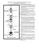
STAS Exploded View
FELT OR GASKET
FELT OR GASKET
FELT OR GASKET
FELT OR GASKET