
User Guide


From
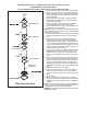
Evaporator
To
Compressor
45° Elbow
Copper Sweat
45° Street Elbow
Copper Sweat
www.emersonclimate.com/owcontrols
STAS Steel Take-Apart Shell with Replaceable Filter-Drier Blocks and Filters
STAS Steel Take-Apart Shell with
Replaceable Filter-Drier Blocks and Filters
Instruction Sheet
PA-00105
October 2011
11911 Adie Road P.O. Box 411400 St. Louis MO 63141 USA CUSTOMER SERVICE (314) 569-4666
Safety Instructions
1. Read Installation Instructions thoroughly. Failure to
follow instructions may result in drier failure or system
damage.
2. Do not remove blocks from can until just prior to instal-
lations. Early removal could result in contamination of
the desiccant from surrounding atmosphere.
3. Checkarrowforcorrectowdirection.Reverse ow
may cause internal damage.
4. CAUTION: In a severely contaminated system avoid
breathing acid vapors, and avoid contact with the skin
or clothing from contaminated refrigerant. Dispose the
contaminated refrigerant in a caustic solution. Failure
to do so may cause personal injury.
5. Thoroughly leak test system after installation. Failure
to do so could result in loss of refrigerant.
6. These products are intended for use on CFC, HCFC,
and HFC refrigerants.
DonotuseEmersonlter-driersonanyotherun-
listedgasoruidmediawithoutpriorapprovalofthe
Emerson Climate Technologies Flow Controls Division
ApplicationsEngineeringDepartment.Useonuids
not listed could result in chemical deterioration of the
lter-drier.
7. The products listed in the bulletin should not be used
for hot gas applications.
Liquid Line Service
1. For best results install the STAS steel take-apart
shell in the liquid line between the receiver and the
moisture-liquid indicator, solenoid valve and thermal
expansion valve. The STAS shell may be mounted in
any position; but the horizontal position is preferred
inthatanycontaminantscollectedbythelter-drier
blocks will be more easily removed when installing
newlter-drierblocks.
NOTE: The side connection of the STAS shell must always
be the inlet when used on liquid line service to ensure
system protection from possible block rupture.
Suction Line Service
1. Locate the STAS shell in the suction line as close as
possible to the compressor, but upstream of any vibra-
tion eliminator that might be present. Install the shell in
a vertical position (outlet down), or as show in Figure 1
which permits oil return to the compressor and conve-
nient removal of the internal hardware assembly.
NOTE: The side connection of the STAS shell must
alwaysbetheinletwhenconventionalsuctionltersare
used,orwhenlter-drierblocksareusedforburnout
clean-up. The side connection may be used as an outlet
ttingonly when a reverse ow lter, F-48R, will be used
to prevent possible rupture with resulting discharge into
the compressor.
1. Install the shell in a location that affords adequate
clearancetoremovetheentireoutletretainer/lter-
drier block assembly as noted below:
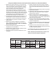
SHELL SIZE REQUIRED CLEARANCE
STAS-48 7 ¼”
STAS-96 12 ¾”
STAS-144 18 ¼”
STAS-192 23 ¾”
2. Removal of the internal components of the STAS shell
is not required before brazing into the system.
3. Purge an inert gas such as nitrogen thru the lines
while brazing to prevent formation of copper oxides.
DO NOT USE OXYGEN.
4. High temperature brazing alloys may be used as the
STASttingsaresolidcopper.Normalprecautions
shouldbetakenbydirectingtheameawayfromthe
lter-driershell,andtheuseofchillblocks,wetrags
or other suitable heat protection to minimize damage
tothepaintsurfacesadjacenttothettingsisrecom-
mended.
5. Test for leakage.
6. Installthelter-drierblocksasnotedonpage2.
NOTE:Ontheinitialinstallationofeitherlter-drierblocks
orltersthecardboardspacersusedtosecurethe
inlet retainer (and couplings as required) should be
discarded.
Figure 1