
Install Instructions
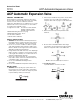

2a) Use a back up wrench on wrench flats and do not
over tighten.
5b.For ODF ACP Valves
WARNING:
The valve body and power head must under
no circumstances be subjected to temperature in excess
of 300°F.
1b) To avoid internal damage of the valve, protct them
with wet cloths, chill blocks or other suitable heat protec-
tor.
2b) Direct flaming braze away from valve body.
6. Check for leaks, sufficient system refrigerant, and be sure
no flash gas is present in liquid at the valve inlet.
7. When viewed from the top, turning the adjusting screw in
a clockwise direction raises the valve outlet pressure and
turning counterclockwise, lowers the outlet pressure.
SERVICE
When it should become necessary to remove the valve or
any part of the valve from the system, all previously men-
tioned Safety and Installation Instructions should be followed
exactly.
J
J
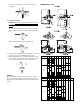
ACP(E) E F G H
VALVE TYPE INLET OUTLET A B DIA. MIN. DIA. MIN. K L M
1/4 1.50
3/8 1.64
1/2 1.72 – – –
1/4 1.50
3/8 1.64
1/2 1.72
1/4 1.25 .25 .32
3/8 .37 .32
3/8 1.19 .37 .32 4.25 1.88 1.48
1/2 .50 .38
1.19
1/2 .50 .38
5/8 5/8 1.38 1.38 .62 .50 .62 .50
1/4 1.25 .25 .32
3/8 1.19 .37 .32
1/4 1/2 1.25 1.19 .25 .32 .50 .38
1/2 .50 .38 .87 .75
3/8 .37 .32 .87 .75
STRAIGHT-THRU
SAE
STRAIGHT-THRU
ODF
3/8
1/2
5/8
1.64
1.72
1.96
7/8 1.19 1.75
ACP(E) E F G H
VALVE TYPE INLET OUTLET A B DIA. MIN. DIA. MIN. K L
1/4 1.50
3/8 1.64
1/2 1.72 –––––
1/4 1.50
3/8 1.64
1/2 1.72
1/4 1.25 .25 .32
3/8 .37 .32
3/8 .37 .32 4.55 2.17
1/2 .50 .38
1.19
1/2 – .50 .38
5/8 5/8 1.38 .62 .50 .62 .50 4.73 2.36
1/4 1.25 .25 .32
3/8 1.19 .37 .32
1/4 1/2 1.25 .25 .32 .50 .38 4.55 2.17
1/2 7/8 1.19 .50 .38 .87 .75 5.11 2.73
ANGLE
SAE
ANGLE
ODF
3/8
3/8 - 1/2
5/8
DIMENSIONAL DATA
4.50 2.13
4.61 2.23