
Full Product Manual
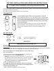

INSTALLATION OF NATURAL GAS PILOT VALVE (cont.)
J. The valve assembly can be rotated to horizontal, and to allow it to rest on the fireplace floor. Simply rotate the
entire valve assembly by turning the 3/8" Street Elbow (connected to burner orifice) with a wrench (See Fig-
ure 8).
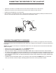
NOTE: The Pilot Bracket utilizes four mounting holes for adjustment of the Pilot Burner Assembly should
your installation require repositioning. Repositioning of the Pilot Burner
Assembly may be necessary if the log set is experiencing intermittent
shutdown. Shutdown is caused by overheating of the Pilot Burner
Assembly by the main burner flame. If shut down is occurring, move
the Pilot Burner Assembly over to the next mounting hole so that only
the tips of the Pilot Burner Assembly are hanging over the Burner Pan.
Only one Mounting Screw (Part #7) will be used in this application.
M. Connect the 1/2" gas supply line from the fireplace to the 3/8" Straight
Flared fitting (Part #24) with the 3/8" Flared Tubing supplied with the
gas log set. Refer to the General Installation Instructions section titled
“Connecting Gas Supply to Burner Pan” for full instructions.
N.
Test connections for leaks with soapy water. Retighten if necessary,
and retest the connections to determine if any other leaks are present.
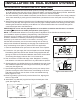
Figure 8 Top View of Valve
Figure 6 Back View of Valve
Figure 7 Front View of valve
Outlet
Inlet
Thermocouple
Connection
Pilot Fitting
Connection
Plug
Gas Control
Knob
Pilot
Adjustment Screw
Knob Position
Indicator
Burner Pan
Street Elbows
Gas Control Valve
Part # 4
INSTALLATION ON DUAL BURNER SYSTEMS
I. Attach the 3/8" Natural Gas Orifice Holder (Part #17) through the washer (Log Kit Part # 21) and Burner Pan
to the Burner Bar using the 3/8" Locknut. Using pipe sealant, connect the Street Elbow (Part #16, attached to
the valve assembly) to the Orifice Holder (part #17 or #19) on the 3/8" NPT threads.
Figure 5 - NG Orifice Holder
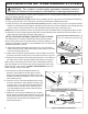
K. Attach Pilot Burner Assembly (Part #5) to the Pilot Bracket (Part #6) using the two machine screws (Part #8)
and two nuts (Part #9). See Figure 3A on the previous page. Carefully bend the Pilot tubing (Part #10) when
attaching the Pilot Burner Assembly to the Burner Pan. Care should be taken not to kink the tubing which
would restrict gas flow to the Pilot Burner.
IMPORTANT: Be sure to turn the pilot adjustment screw with a screwdriver two full turns in a counter-
clockwise direction to enable pilot operation (See Figure 7).
L. Place the assembled burner pan back into the center of the fireplace.
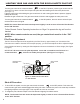
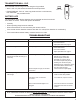
Figure 9
Figure 10
P.
Spread Glowing Embers (Log Kit Part #17) evenly over the top of the
granules covering the entire surface area, concentrating on the front
and sides of the burner pan as shown for the most realistic burning
R
.
. Place Log Grate (Log Kit Part #7) over the Burner Pan, aligning it as
shown in Figure 9B.
Q.
Attach Back Log Standoff (Log Kit Part #18) to the back part of the
grate (See Figure 9B).
O
. Spread granules (Log Kit Part #16) over the installed burner pan. Gran-
ules should be sloped to the same angle as the burner pan filling the
entire pan (See Figure 9A).
effect (Figures 9 & 10).
Orifice
3