
Installation Guide

INSTALLATION
Continued
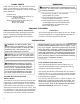
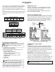
5. Turn pressure selecting screw over and reinstall it
in regulator cap (see Figure 10-11).This will set the
pressure selecting screw to the LP/Propane gas
position.
Make sure the pressure selecting screw is
installed tightly to the regulator cap.
6. Replace the regulator cap on the appliance regulator.
Figure 9 - Gas Selection Valve Knob and
Regulator Cap
Regulator
Cap
Pressure
Selecting
Screw
Appliance
Regulator
Figure 10 - Removing Regulator Cap from Pressure
Selecting Screw
Figure 11 - Turning Pressure Selecting Screw Over/
Attaching to Regulator Cap – LP/Propane
Gas Position
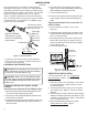
1. Generously apply soapy solution to all connect-
ions.
WARNING: Never check for gas
leaks with open flame.
2. Light burner with shutof f valve no more t han half
open and holding a match slightly in front of pan
(see
Lighting Instructions , page 17).
3. Inspect all connections for bubbles, raw gas odor,
or flame from any area other than the burner (leaks).
If leaks are detected, shut off gas valve immediately.
tighten, or reassemble loose connection(s) using pipe
joint compound until burner system is leak free.
Testing Burner for Leaks
4. When burner is tested and leak free, observe
individual tongues of flame on burner (from ports).
reaming ports with a modified paper clip or other suit-
able tool. When finished testing, turn gas shutoff
valve to OFF to extinguish all flames.
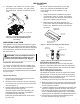
1. Open bag of burner media material (vermiculite
if set for LP/
Propane) and spread it evenly
across burner pan to the top. You may over-
flow front and sides of pan to cover entire pan.
Do not cover valve.
2. Open glowing embers and evenly cover burner
media material (or vermiculite) in burner pan.
Adding Burner Media Material
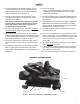
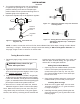
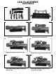
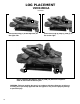
Installing Grate and logs
Slide two rear log grate steps over two outer
horizontal supports on t h e grate as shown
in image 2 on page 9.
Install logs onto the grate by following the rest
of the instructions for your log set model on the
following pages.
1.
2.
8
NOTE: In order to convert the unit from LP Gas, back to Natural Gas, follow steps 1 through 3 under “Burner
Inlet Fitting” on Page 7. Follow steps 1 through 6 under the heading of “NG to LP Regulator Selection” on
this page. Images 10 and 11 will occur in reverse order.
Note: Make sure that all port s are clear and prod-
ucing flame evenly across burner. If any ports appear
blocked, clear them by removing burner manifold and