
Installation Guide
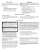
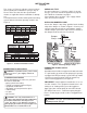

We recommend that you install a sediment trap in
the supply line as shown in Figure 4. Locate sediment
trap where it is within reach for cleaning. Install in piping
system between fuel supply and heater. Locate sed-
iment trap where trapped matter is not likely to
freeze. A sediment trap traps moisture and contamin-
ants. This keeps them from going into log set controls.
If sediment trap is not installed or is installed wrong,
log set may not run properly.
INSTALLATION
Figure 4 - Gas Connection
3" Minimum
From Gas
Meter (5"
W.C.** to
10.5" W.C.
Pressure)
CSA Design-Certified
Equipment Shutoff Valve
With 1/8" NPT Tap*
Approved Flexible
Gas Hose (no longer
than 36" if required by
local codes)
Tee Pipe Cap
Joint Nipple
Sediment Trap
* Purchase the optional CSA design-certified equipment
shutoff valve from your dealer. ** Minimum inlet pressure
for purpose of input adjustment.
6
CHECKING GAS CONNECTIONS
WARNING:Test allgas piping and connections, in-
ternal and external to unit, for leaks after installing
or servicing. Correct all leaks at once.
WARNING: Never use an open flame to check
for a leak. Applyanoncorrosiveleakdetection fluid to
all joints. Bubbles forming show a leak. Correct all
leaks at once.
PRESSURE TESTING GAS SUPPLY PIPING
SYSTEM
Test Pressures In Excess Of 1/2 PSIG (3.5 kPa)
1. Disconnect log set and its individual equipment shut-
off valve from gas supply piping system.
-
2. Cap off open end of gas pipe where equipment shut-
off valve was connected.
-
3. Pressurize supply piping system by either using com-
pressed air or opening main gas valve located on or
near gas meter.
Continued
4. Check all joints of gas supply piping system.
Apply a noncorrosive leak detection fluid to all
joints. Bubbles forming show a leak.
-
5. Correct all leaks at once.
6. Reconnect log set and equipment shutoff valve
to gas supply. Check reconnected fittings for
leaks.
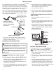
Test Pressures Equal To or Less Than 1/2
PSIG (3.5 kPa)
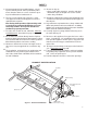
1. Close equipment shutoff valve (see
Figure 5).
2. Pressurize supply piping system by either using
compressed air or opening main gas valve locat-
ed on or near gas meter.
3. Check all joints from gas meter to equip ment
shutoff valve (see Figure 5). Apply a noncorr-
osive leak detection fluid to all joints. Bubbles
forming show a leak.
-
4. Correct all leaks at once.
Figure 5 - Checking Gas Joints
Gas Meter
Equipment
Shutoff Valve
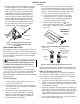
HEARTH
PAN I NSTALLATION
If using propane/LP gas, (see
page 7) before installing hearth pan.
1. Place the burner pan assembly in the center
of the fireplace floor. Make sure the front of
pan faces forward.
2. Thread the gas supply fitting to the fire place
gas supply pipe. Adjust to most convenient
position.
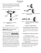
Install the Natural Gas burner orifice (see Fig-
ure 7, page 8) provided with your Log Set)
into NG Orifice holder (Part # 5).
Attach the 3/8"
Natural Gas Orifice Holder (Part # 5) through
the Burner Pan (Part # 1) to the Burner Bar( Part
) using the 3/8" Locknut (
Part #8).
3.
Selecting Gas
Type
# 2